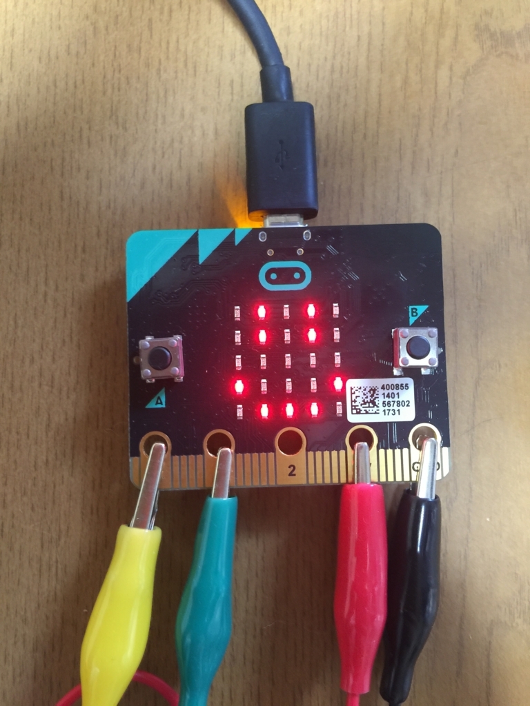
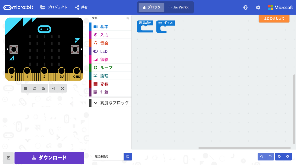
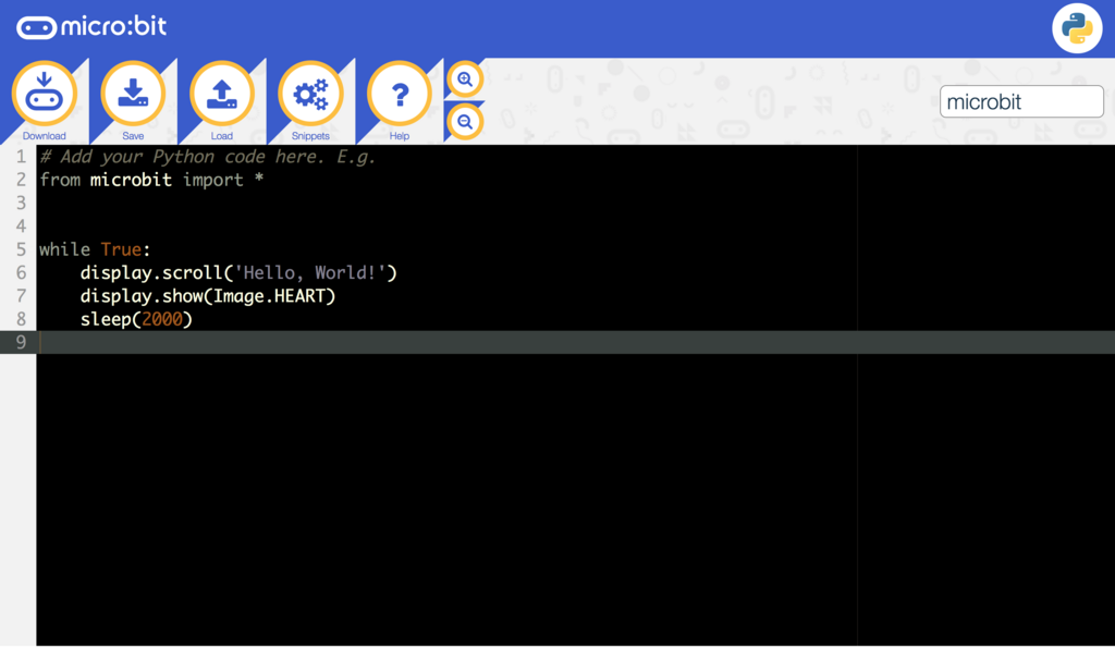
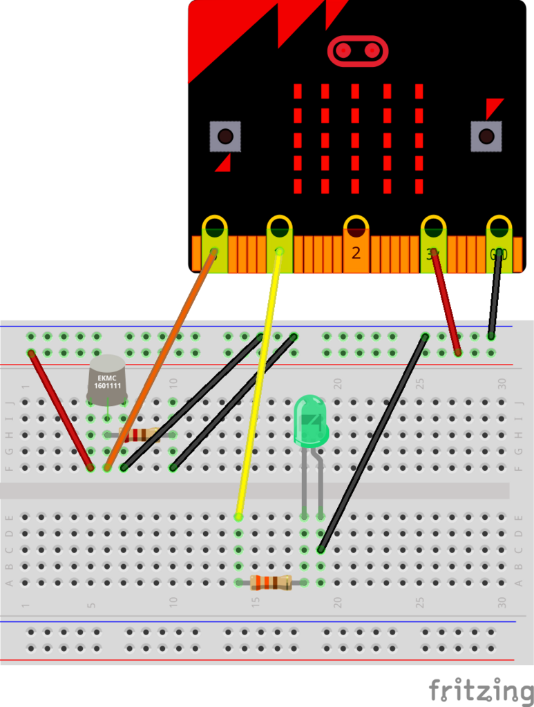
yotta で micro:bit を mbed オフラインビルドする

 前回オンラインエディタで micro:bit のプログラムをビルドして動作させてみましたが、 micro:bit は mbed にも対応しているので、今回は mbed を使ってオフライン環境で CLI からビルドしてみたいと思います。 mbed の Web IDE もかなり優秀だと思うのですが、意図せずブラウザバックしてしまったりなどブラウザの操作性に依存するところがあるのと、今まで CLI で vim を使ってコードを書いていたので、継続的にコードを書いていくのであればやはりオフラインビルド環境を作りたくなってしまいます。

mbed CLI だとエラー

 まずは以前 BLE Nano の時に使った mbed CLI を使おうと色々と試してみました。

 micro:bit は mbed OS 5 に対応していないので、 mbed OS 5 のプロジェクトとして作成してターゲットを micro:bit にしていると、コンパイル時に怒られます。

[vagrant@localhost vagrant]$ mbed new microbit_sample
[mbed] Creating new program "microbit_sample" (git)
[mbed] Adding library "mbed-os" from "https://github.com/ARMmbed/mbed-os" at branch latest
[mbed] Updating reference "mbed-os" -> "https://github.com/ARMmbed/mbed-os/#6e0d01cd13e8aca7bf4d697c3699ec9225386881"
[vagrant@localhost vagrant]$ 
[vagrant@localhost vagrant]$ cd microbit_sample/
[vagrant@localhost microbit_sample]$ 
[vagrant@localhost microbit_sample]$ mbed toolchain GCC_ARM                                                                                                                                                                                   
[mbed] GCC_ARM now set as default toolchain in program "microbit_sample"
[vagrant@localhost microbit_sample]$ mbed target NRF51_MICROBIT
[mbed] NRF51_MICROBIT now set as default target in program "microbit_sample"
[vagrant@localhost microbit_sample]$ 
[vagrant@localhost microbit_sample]$ mbed compile
Building project microbit_sample (NRF51_MICROBIT, GCC_ARM)
Scan: .
Scan: env
Scan: mbed
Scan: FEATURE_BLE

Could not compile for NRF51_MICROBIT: Target does not support mbed OS 5

 次に BLE Nano の時と同様に、 mbed OS 2 のプロジェクトとして mbed のライブラリを落としてくる方法を試してみましたが、コンパイル時にエラーになってしまいます。

[vagrant@localhost vagrant]$ mbed new microbit_sample --mbedlib
[mbed] Creating new program "microbit_sample" (git)
[mbed] Adding library "mbed" from "https://mbed.org/users/mbed_official/code/mbed/builds" at latest revision in the current branch
[mbed] Updating reference "mbed" -> "https://mbed.org/users/mbed_official/code/mbed/builds/tip"
[mbed] Couldn't find build tools in your program. Downloading the mbed 2.0 SDK tools...
[vagrant@localhost vagrant]$ 
[vagrant@localhost vagrant]$ cd microbit_sample/
[vagrant@localhost microbit_sample]$ 
[vagrant@localhost microbit_sample]$ mbed deploy
[mbed] Updating library "mbed" to branch tip
[mbed] Downloading library build "fb8e0ae1cceb" (might take a minute)
[mbed] Unpacking library build "fb8e0ae1cceb" in "/vagrant/microbit_sample/mbed"
[mbed] Updating the mbed 2.0 SDK tools...
[vagrant@localhost microbit_sample]$ 
[vagrant@localhost microbit_sample]$ mbed add http://mbed.org/teams/Lancaster-University/code/microbit/
[mbed] Adding library "microbit" from "https://mbed.org/teams/Lancaster-University/code/microbit" at latest revision in the current branch
[mbed] Adding library "microbit/microbit-dal" from "https://developer.mbed.org/teams/Lancaster-University/code/microbit-dal" at rev #eb91bba49623
[mbed] Adding library "microbit/microbit-dal/BLE_API" from "https://developer.mbed.org/teams/Lancaster-University/code/BLE_API" at rev #dd2f69fad8c6
[mbed] Adding library "microbit/microbit-dal/mbed-dev-bin" from "https://developer.mbed.org/teams/Lancaster-University/code/mbed-dev-bin" at rev #768173a57492
[mbed] Adding library "microbit/microbit-dal/nRF51822" from "https://developer.mbed.org/teams/Lancaster-University/code/nRF51822" at rev #b84f72a53341
[mbed] Adding library "microbit/microbit-dal/nRF51822/nrf51-sdk" from "https://developer.mbed.org/teams/Lancaster-University/code/nrf51-sdk" at rev #54ddd6f8268c
[mbed] Updating reference "microbit" -> "https://mbed.org/teams/Lancaster-University/code/microbit/#4b89e7e3494f"
[vagrant@localhost microbit_sample]$ 
[vagrant@localhost microbit_sample]$ mbed toolchain GCC_ARM                                                                                                                                                                                   
[mbed] GCC_ARM now set as default toolchain in program "microbit_sample"
[vagrant@localhost microbit_sample]$ mbed target NRF51_MICROBIT
[mbed] NRF51_MICROBIT now set as default target in program "microbit_sample"
[vagrant@localhost microbit_sample]$ 
[vagrant@localhost microbit_sample]$ mbed compile
Building project microbit_sample (NRF51_MICROBIT, GCC_ARM)
Scan: .
Scan: mbed
Scan: env
Compile [  1.0%]: main.cpp
[Error] MicroBitMatrixMaps.h@73,49: 'p13' was not declared in this scope
[Error] MicroBitMatrixMaps.h@74,49: 'p4' was not declared in this scope
[ERROR] In file included from ./microbit/microbit-dal/inc/core/MicroBitDevice.h:42:0,
                 from ./microbit/inc/MicroBit.h:33,
                 from ./main.cpp:1:
./microbit/microbit-dal/inc/drivers/MicroBitMatrixMaps.h:73:49: error: 'p13' was not declared in this scope
 #define MICROBIT_DISPLAY_ROW1                   p13
                                                 ^
./microbit/microbit-dal/inc/drivers/MicroBitMatrixMaps.h:155:5: note: in expansion of macro 'MICROBIT_DISPLAY_ROW1'
     MICROBIT_DISPLAY_ROW1,
     ^
./microbit/microbit-dal/inc/drivers/MicroBitMatrixMaps.h:74:49: error: 'p4' was not declared in this scope
 #define MICROBIT_DISPLAY_COL1                   p4
                                                 ^
./microbit/microbit-dal/inc/drivers/MicroBitMatrixMaps.h:156:5: note: in expansion of macro 'MICROBIT_DISPLAY_COL1'
     MICROBIT_DISPLAY_COL1,
     ^

[mbed] ERROR: "/usr/local/pyenv/versions/anaconda2-4.4.0/bin/python" returned error code 1.
[mbed] ERROR: Command "/usr/local/pyenv/versions/anaconda2-4.4.0/bin/python -u /vagrant/microbit_sample/.temp/tools/make.py -t GCC_ARM -m NRF51_MICROBIT --source . --build ./BUILD/NRF51_MICROBIT/GCC_ARM" in "/vagrant/microbit_sample"
---

 これは mbed のライブラリと micro:bit のライブラリでピンの定義が異なっているためです。 mbed のライブラリでは下記のように GPIO ピンが大文字で定義されています。

    //MCU PINS
    P0_0  = 0,
    P0_1  = 1,
    P0_2  = 2,
    P0_3  = 3,
    P0_4  = 4,
    P0_5  = 5,
    P0_6  = 6,
    P0_7  = 7,
    P0_8  = 8,
    P0_9  = 9,
    P0_10 = 10,
    P0_11 = 11,
    P0_12 = 12,
    P0_13 = 13,
    P0_14 = 14,
    P0_15 = 15,
    P0_16 = 16,
    P0_17 = 17,
    P0_18 = 18,
    P0_19 = 19,
    P0_20 = 20,
    P0_21 = 21,
    P0_22 = 22,
    P0_23 = 23,
    P0_24 = 24,
    P0_25 = 25,
    P0_26 = 26,
    P0_27 = 27,
    P0_28 = 28,
    P0_29 = 29,
    P0_30 = 30, 

mbed - a mercurial repository | Mbed

 それに対して、 micro:bit のライブラリでは小文字でアサインされていることを期待しているためです。

#define MICROBIT_DISPLAY_ROW1                   p13
#define MICROBIT_DISPLAY_COL1                   p4

microbit-dal - a mercurial repository | Mbed

 調べてみた限りでは、 micro:bit のライブラリの最終更新は15ヶ月前なのですが、その後の mbed のライブラリの更新で、ピンの定義が小文字から大文字に変更されたようです。

https://os.mbed.com/users/mbed_official/code/mbed/diff/d75b3fe1f5cb/TARGET_NRF51_MICROBIT/TARGET_NORDIC/TARGET_MCU_NRF51822/TARGET_NRF51_MICROBIT/PinNames.h

 なので今度は mbed の公式ライブラリを使わず、 micro:bit が fork しているライブラリが使われるように、 mbed new の際に --create-only オプションをつけて mbed ライブラリを使わずにプロジェクトを作成し、後から micro:bit 用に用意されているライブラリを mbed add してみました。

[vagrant@localhost vagrant]$ mbed new microbit_sample --create-only
[mbed] Creating new program "microbit_sample" (git)
[mbed] Couldn't find build tools in your program. Downloading the mbed 2.0 SDK tools...
[vagrant@localhost vagrant]$ 
[vagrant@localhost vagrant]$ cd microbit_sample/
[vagrant@localhost microbit_sample]$ 
[vagrant@localhost microbit_sample]$ mbed add http://mbed.org/teams/Lancaster-University/code/microbit/
[mbed] Adding library "microbit" from "https://mbed.org/teams/Lancaster-University/code/microbit" at latest revision in the current branch
[mbed] Adding library "microbit/microbit-dal" from "https://developer.mbed.org/teams/Lancaster-University/code/microbit-dal" at rev #eb91bba49623
[mbed] Adding library "microbit/microbit-dal/BLE_API" from "https://developer.mbed.org/teams/Lancaster-University/code/BLE_API" at rev #dd2f69fad8c6
[mbed] Adding library "microbit/microbit-dal/mbed-dev-bin" from "https://developer.mbed.org/teams/Lancaster-University/code/mbed-dev-bin" at rev #768173a57492
[mbed] Adding library "microbit/microbit-dal/nRF51822" from "https://developer.mbed.org/teams/Lancaster-University/code/nRF51822" at rev #b84f72a53341
[mbed] Adding library "microbit/microbit-dal/nRF51822/nrf51-sdk" from "https://developer.mbed.org/teams/Lancaster-University/code/nrf51-sdk" at rev #54ddd6f8268c
[mbed] Updating reference "microbit" -> "https://mbed.org/teams/Lancaster-University/code/microbit/#4b89e7e3494f"
[vagrant@localhost microbit_sample]$ 
[vagrant@localhost microbit_sample]$ mbed toolchain GCC_ARM
[mbed] GCC_ARM now set as default toolchain in program "microbit_sample"
[vagrant@localhost microbit_sample]$ mbed target NRF51_MICROBIT
[mbed] NRF51_MICROBIT now set as default target in program "microbit_sample"
[vagrant@localhost microbit_sample]$ 
[vagrant@localhost microbit_sample]$ mbed compile
Building project microbit_sample (NRF51_MICROBIT, GCC_ARM)
Scan: .
Scan: mbed
Scan: env
Compile [  1.0%]: main.cpp
Compile [  2.0%]: BLE.cpp
Compile [  3.0%]: DiscoveredCharacteristic.cpp
Compile [  4.0%]: GapScanningParams.cpp
Compile [  5.1%]: DFUService.cpp
[Error] ble_dfu.h@190,44: 'ble_evt_t' has not been declared
[Error] device_manager.h@509,25: variable or field 'dm_ble_evt_handler' declared void
[Error] device_manager.h@509,0: 'ble_evt_t' was not declared in this scope
[Error] device_manager.h@509,37: 'p_ble_evt' was not declared in this scope
[ERROR] In file included from ./microbit/microbit-dal/nRF51822/nrf51-sdk/source/nordic_sdk/components/libraries/bootloader_dfu/dfu_app_handler.h:57:0,
                 from ./microbit/microbit-dal/BLE_API/ble/services/DFUService.h:26,
                 from ./microbit/microbit-dal/BLE_API/source/services/DFUService.cpp:19:
./microbit/microbit-dal/nRF51822/nrf51-sdk/source/nordic_sdk/components/ble/ble_services/ble_dfu/ble_dfu.h:190:44: error: 'ble_evt_t' has not been declared
 void ble_dfu_on_ble_evt(ble_dfu_t * p_dfu, ble_evt_t * p_ble_evt);
                                            ^
In file included from ./microbit/microbit-dal/nRF51822/nrf51-sdk/source/nordic_sdk/components/libraries/bootloader_dfu/dfu_app_handler.h:60:0,
                 from ./microbit/microbit-dal/BLE_API/ble/services/DFUService.h:26,
                 from ./microbit/microbit-dal/BLE_API/source/services/DFUService.cpp:19:
./microbit/microbit-dal/nRF51822/nrf51-sdk/source/nordic_sdk/components/ble/device_manager/device_manager.h:509:25: error: variable or field 'dm_ble_evt_handler' declared void
 void dm_ble_evt_handler(ble_evt_t * p_ble_evt);
                         ^
./microbit/microbit-dal/nRF51822/nrf51-sdk/source/nordic_sdk/components/ble/device_manager/device_manager.h:509:25: error: 'ble_evt_t' was not declared in this scope
./microbit/microbit-dal/nRF51822/nrf51-sdk/source/nordic_sdk/components/ble/device_manager/device_manager.h:509:37: error: 'p_ble_evt' was not declared in this scope
 void dm_ble_evt_handler(ble_evt_t * p_ble_evt);
                                     ^

[mbed] ERROR: "/usr/local/pyenv/versions/anaconda2-4.4.0/bin/python" returned error code 1.
[mbed] ERROR: Command "/usr/local/pyenv/versions/anaconda2-4.4.0/bin/python -u /vagrant/microbit_sample/.temp/tools/make.py -t GCC_ARM -m NRF51_MICROBIT --source . --build ./BUILD/NRF51_MICROBIT/GCC_ARM" in "/vagrant/microbit_sample"
---

 ですが ble_evt_t が定義されていないということでコンパイルエラーになってしまいました。解決方法も探してみたのですが、この問題を直接的に解決する方法が見つからなかったので、一旦 mbed CLI を使う方法は諦めます。

yotta 環境構築

 上記エラーの解決方法を探していたところ、 Lancaster University の github で環境構築についてのドキュメントが公開されていました。

lancaster-university.github.io

 その中で yotta を使ってオフラインビルドする方法が公開されていました。

Offline Development - micro:bit runtime

 なのでまずは下記ドキュメントに沿って yotta の環境を構築します。今回は Vagrant を使って ubuntu の VM上に環境を構築しました。

yotta Documentation - yotta

 詳細な手順は上記サイトをご覧いただくとして割愛しますが、大まかな内容としては python や pip、 yotta に必要なライブラリ、コンパイラをインストールした上で、 pip で yotta をインストールします。

プロジェクトの作成とビルド

 yotta の環境が構築できたらまずはシンプルなプロジェクトを作成してビルドしてみます。最初にプロジェクトのディレクトリを作成して初期化します。

vagrant@vagrant:/vagrant$ mkdir microbit-init-sample
vagrant@vagrant:/vagrant$                           
vagrant@vagrant:/vagrant$ cd microbit-init-sample/
vagrant@vagrant:/vagrant/microbit-init-sample$    
vagrant@vagrant:/vagrant/microbit-init-sample$ yotta init                      
Enter the module name: <microbit-init-sample>                                  
Enter the initial version: <0.0.0>                                             
Is this an executable (instead of a re-usable library module)? <no> yes        
Short description: microbit sample                                             
Author: Akanuma Hiroaki                                                        
What is the license for this project (Apache-2.0, ISC, MIT etc.)?  <Apache-2.0>
vagrant@vagrant:/vagrant/microbit-init-sample$                                 

 そしてビルドターゲットを micro:bit に設定します。

vagrant@vagrant:/vagrant/microbit-init-sample$ yt target bbc-microbit-classic-gcc 
info: get versions for bbc-microbit-classic-gcc
info: download bbc-microbit-classic-gcc@0.2.3 from the public module registry
info: get versions for mbed-gcc
info: download mbed-gcc@0.1.3 from the public module registry

 次に micro:bit のライブラリをインストールします。

vagrant@vagrant:/vagrant/microbit-init-sample$ yt install lancaster-university/microbit
info: microbit, lancaster-university/microbit
info: get versions for microbit
info: download microbit@v2.0.0-rc9 from GitHub lancaster-university/microbit
info: dependency microbit: lancaster-university/microbit written to module.json
info: get versions for microbit-dal
info: download microbit-dal@v2.0.0-rc9 from GitHub lancaster-university/microbit-dal
info: get versions for mbed-classic
info: download mbed-classic@microbit_hfclk+mb6 from GitHub lancaster-university/mbed-classic
info: get versions for ble
info: download ble@v2.5.0+mb3 from GitHub lancaster-university/BLE_API
info: get versions for ble-nrf51822
info: download ble-nrf51822@v2.5.0+mb7 from GitHub lancaster-university/nRF51822
info: get versions for nrf51-sdk
info: download nrf51-sdk@v2.2.0+mb4 from GitHub lancaster-university/nrf51-sdk

 ビルドするプログラムとして下記のように簡単なコードを書いてみました。「Hello, world!!」という文字列をスクロールで一度表示するだけのものです。

ainclude "MicroBit.h"

MicroBit uBit;

int main()
{
  uBit.init();

  uBit.display.scroll("Hello, world!!");

  release_fiber();
}

 そして下記コマンドでビルドします。

vagrant@vagrant:/vagrant/microbit-init-sample$ yt build 

 無事にコンパイルが完了すると下記のように .hex ファイルが作成されます。

vagrant@vagrant:/vagrant/microbit-init-sample$ ls -l build/bbc-microbit-classic-gcc/source/microbit-init-sample-combined.hex 
-rw-r--r-- 1 vagrant vagrant 494768 Nov  1 21:26 build/bbc-microbit-classic-gcc/source/microbit-init-sample-combined.hex

 この .hex ファイルを micro:bit にコピーするとプログラムが動作します。

vagrant@vagrant:/vagrant/microbit-init-sample$ cp build/bbc-microbit-classic-gcc/source/microbit-init-sample-combined.hex /media/vagrant/MICROBIT/.

焦電センサーとの組み合わせ

 とりあえずオフラインビルドができるようになったので、前回ブロックエディタでやった焦電センサーとの組み合わせを、 mbed で実装してみたいと思います。センサー等の配線は前回と同様で、コード全体は下記の通りです。

#include "MicroBit.h"

MicroBit uBit;

MicroBitPin P0(MICROBIT_ID_IO_P0, MICROBIT_PIN_P0, PIN_CAPABILITY_ANALOG);
MicroBitPin P1(MICROBIT_ID_IO_P1, MICROBIT_PIN_P1, PIN_CAPABILITY_DIGITAL);

MicroBitImage smiley("0,255,0,255, 0\n0,255,0,255,0\n0,0,0,0,0\n255,0,0,0,255\n0,255,255,255,0\n");
MicroBitImage closing_eyes("0,0,0,0, 0\n255,255,0,255,255\n0,0,0,0,0\n0,255,255,255,0\n0,0,0,0,0\n");

int pyro_value = 0;

int main()
{
  uBit.init();
  uBit.serial.send("Starting micro:bit pyroelectric.\r\n");
  uBit.display.scroll("HELLO!");

  while(true) {
    pyro_value = P0.getAnalogValue();
    uBit.serial.printf("%d\r\n", pyro_value);

    if (pyro_value >= 500) {
      P1.setDigitalValue(1);
      uBit.display.print(smiley);
    } else {
      P1.setDigitalValue(0);
      uBit.display.print(closing_eyes);
    }

    uBit.sleep(1000);
  }
}

 まず使用するピンを初期化しています。 P0 は焦電センサーからアナログ値を読み取るため PIN_CAPABILITY_ANALOG を指定し、 P1 はブレッドボード上の LED の点灯/消灯のデジタル出力なので PIN_CAPABILITY_DIGITAL を指定しています。

MicroBitPin P0(MICROBIT_ID_IO_P0, MICROBIT_PIN_P0, PIN_CAPABILITY_ANALOG);
MicroBitPin P1(MICROBIT_ID_IO_P1, MICROBIT_PIN_P1, PIN_CAPABILITY_DIGITAL);

 焦電センサーでの検知時/非検知時に表示する顔のイメージもあらかじめ定義しておきます。

MicroBitImage smiley("0,255,0,255, 0\n0,255,0,255,0\n0,0,0,0,0\n255,0,0,0,255\n0,255,255,255,0\n");
MicroBitImage closing_eyes("0,0,0,0, 0\n255,255,0,255,255\n0,0,0,0,0\n0,255,255,255,0\n0,0,0,0,0\n");

 デバッグ用にシリアル接続も使用しています。 uBit.serial.send() もしくは uBit.serial.printf() で文字列を出力しておくと、 screen コマンドで micro:bit に接続して出力を確認することができます。

  uBit.serial.send("Starting micro:bit pyroelectric.\r\n");

 あとは無限ループの中で焦電センサー(P0)からアナログ値を読み取り、その値によってブレッドボード上の LED と micro:bit 上の LED の表示を切り替えます。

  while(true) {
    pyro_value = P0.getAnalogValue();
    uBit.serial.printf("%d\r\n", pyro_value);

    if (pyro_value >= 500) {
      P1.setDigitalValue(1);
      uBit.display.print(smiley);
    } else {
      P1.setDigitalValue(0);
      uBit.display.print(closing_eyes);
    }

    uBit.sleep(1000);
  }

 これをビルドして .hex ファイルを micro:bit にコピーすると、焦電センサーの検知状態によって micro:bit の LED の表示が切り替わります。

f:id:akanuma-hiroaki:20171105110146j:plain:w300 f:id:akanuma-hiroaki:20171105110200j:plain:w300

まとめ

 micro:bit は元々の目的が教育用なので、 CLI でがっつり開発することはあまり想定されていないかもしれませんが、色々な機能を持っているので、 mbed から色々試してみるのも面白そうです。とりあえず今回の環境構築に使った Vagrantfile などを下記リポジトリに公開しましたので、参考にしていただければと思います。

github.com

 ハロウィンも終わって次はクリスマスですねー。

f:id:akanuma-hiroaki:20171105140436j:plain:w450

micro:bit + 焦電センサーで人感センサー

 最近 micro:bit を購入したので、今回は micro:bit と焦電センサーを組み合わせて、以前の記事でやったような人感センサーを作ってみたいと思います。

blog.akanumahiroaki.com

micro:bit とは

 micro:bit とは、イギリスBBCが主体となって教育用に作られたマイコンボードで、イギリスでは11歳〜12歳の生徒に無償で配布されているものです。

The Micro:bit Foundation is a global non-profit organisation making invention with technology fun for everyone!

 日本では今年(2017年)の8月から展開を開始していて、私はスイッチサイエンスのサイトから購入しました。

www.switch-science.com

 本体には電光掲示板的に使える25個のLEDや、2つのスイッチに加え、照度センサーや加速度センサー、温度センサーなどを備えています。BLEにも対応していますので、本体機能だけでもアイディア次第で色々なものが作れるのではないかと思います。さらに GPIO 等の外部インタフェースにより他のセンサー等と組み合わせることもできます。

機能 | micro:bit

初期設定

 下記クイックスタートのページでも手順が紹介されていますが、初期設定というほどのものは特になく、マイクロUSBでPCと接続すればすぐにプログラミングをスタートすることが可能です。

クイックスタート | micro:bit

 開発環境もブラウザで動作する Web IDE が用意されているので、複雑な開発環境の設定もありません。

エディタの種類

 Web IDE としては、Javascript ブロックエディタと Python エディタが用意されています。

プログラムしましょう | micro:bit

 Javascript ブロックエディタはブロックを配置することでコードを書かずにプログラミング可能で、視覚的にプログラムを作成することができます。さらに画面左にはエミュレータもあるので、毎回コンパイル&ダウンロードしなくても、書いたコードがどのように動作するのか簡単に確認できます。

f:id:akanuma-hiroaki:20171029225509p:plain

 Python エディタは Python のコードを直接書くことができる Web IDE です。今のところ Python エディタは Bluetooth 機能をサポートしていないということなので、 Bluetooth 機能を使いたい場合には Javascript ブロックエディタを使うことになるかと思います。

f:id:akanuma-hiroaki:20171029225531p:plain

 また、micro:bit は mbed に対応していますので、 mbed の Web IDE を使うことも可能です。ちなみに mbed os 5 には対応していないようなので、mbed os 2 を使う必要がありそうです。

www.mbed.com

 どのエディタを使う場合でも、プログラムを作成したらコンパイルして作成される .hex ファイルをUSBドライブとして認識されている micro:bit に保存するだけで、プログラムが動作を始めます。

 今回は micro:bit 初回ということで、一番ベーシックな Javascript ブロックエディタを使ってみたいと思います。

配線する

 それでは焦電センサーと組み合わせて人感センサーを作るための配線をしてみます。ワニクリップで micro:bit のラージピンとブレッドボードを下記の図のように配線します。焦電センサーと LED の基本的な配線は以前の記事と同様で、電源の供給元を micro:bit の 3V ピン、GND を micro:bit の GND ピンに接続しています。また、焦電センサーと動作確認用のLEDにはそれぞれ0番ピンと1番ピンを接続しています。

f:id:akanuma-hiroaki:20171029223947p:plain:w300

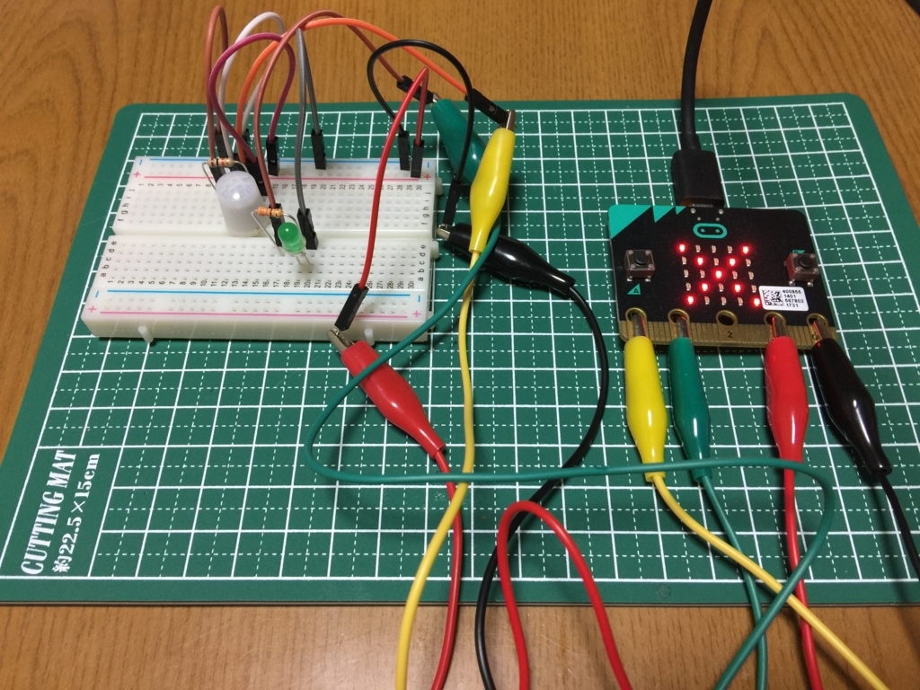
 実際に配線してみた様子は下記の写真のようになります。ごちゃごちゃしててよくわかりませんが参考まで。

f:id:akanuma-hiroaki:20171029224258j:plain:w450

ブロックエディターでコーディング

 配線が完了したところで、ブロックエディタからコーディングします。ブロックエディタではGPIOを操作するパーツも用意されていて、 入出力端子 メニューから選択可能です。

f:id:akanuma-hiroaki:20171029224017p:plain:w450

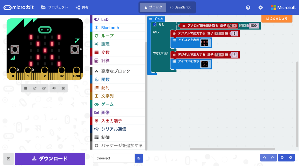
 これらのパーツを使用して下記のようにブロックを配置してプログラムを作成します。

f:id:akanuma-hiroaki:20171029224045p:plain:w450

 ブロックエディタではブロック表示ではなく Javascript を直接コーディングする方法に切り替えることもできますが、 Javascript のコードに切り替えると下記のような内容になっています。

basic.forever(() => {
    if (pins.analogReadPin(AnalogPin.P0) >= 500) {
        pins.digitalWritePin(DigitalPin.P1, 1)
        basic.showIcon(IconNames.Heart)
    } else {
        pins.digitalWritePin(DigitalPin.P1, 0)
        basic.showIcon(IconNames.No)
    }
})

 やっている内容は以前の記事と同様で、焦電センサーからのアナログ入力値が500を超えた場合には人がいるという判定で、ブレッドポード上の LED を点灯させ、 micro:bit の LED にハートマークを表示します。また、下回った場合にはブレッドボード上の LED を消灯して、 micro:bit の LED には × を表示します。

動かしてみる

 それではブロックエディタの ダウンロード ボタンをクリックして、作成したコードをコンパイルし、 hex ファイルを micro:bit に保存して動作させてみます。実際に動かしてみた様子はこちら。

 センサーの前で手を動かすとブレッドボード上の LED と micro:bit の LED の表示が切り替わっています。

まとめ

 micro:bit は使い始めるまでの準備をほとんど必要なく、すぐに開発できる環境がありますし、ブロックエディタを使えばコーディングの経験がなくても視覚的に理解できるので、プログラミング初心者や子ども向けの入門教材としてはとっつきやすいと思いますし、それでいて多機能なので、アイディア次第では色々なものが作れると思います。普通にコードを書ける人はブロックエディタよりも Javascript や Python を直接コーディングする方がスッキリかけて良さそうです。

 本当は今回は mbed CLI で環境を作って動かそうと思ったのですが、mbed OS 2 の環境がうまく動かせずにひとまず断念しました。個人的には CLI 環境で vim で書くのが好きなので、もう少し mbed CLI の環境構築に挑戦してみたいと思います。

f:id:akanuma-hiroaki:20171030074135j:plain:w450

I2C 接続の有機EL + Raspberry Pi + Ruby で温度計付き時計を実装してみる

 今回は Raspberry Pi と OLED(有機EL)ディスプレイを接続して表示させてみたいと思います。使用したディスプレイは aitendo さんで販売されていた下記パーツです。

www.aitendo.com

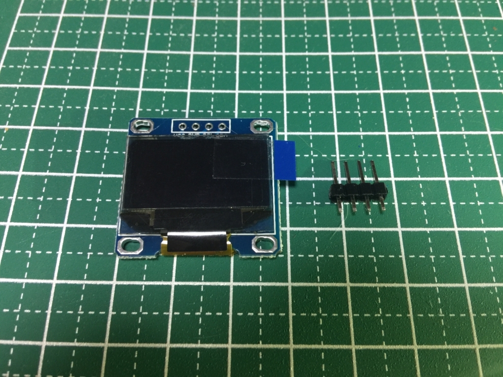
 購入時は下記写真のように、ディスプレイとピンヘッダが同封されていますが別々になっていますので、自分で半田付けして使用します。

f:id:akanuma-hiroaki:20171014221626j:plain:w450

Raspberry Pi と接続

 それでは Raspberry Pi と OLED ディスプレイを接続します。今回下記サイトを参考にさせていただきました。

Overview | SSD1306 OLED Displays with Raspberry Pi and BeagleBone Black | Adafruit Learning System

raspberry pi でI2C接続の有機ELを使って時計を作る - Qiita

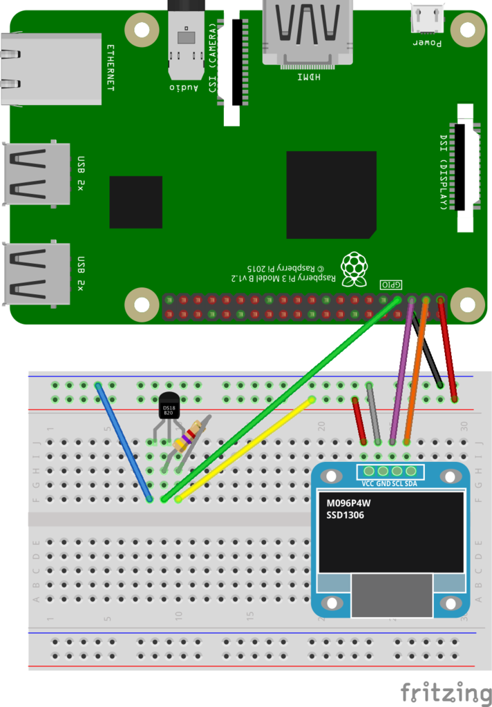
 実際の配線は下記のようにシンプルです。今回使用しているディスプレイは I2C 接続なので、Raspberry Pi では 3番(SDA)と5番(SCL)のピンを使うことになります。

f:id:akanuma-hiroaki:20171015015610p:plain:w300:left

VCC: 1番ピン(3.3V Power)
GND: 6番ピン(GND)
SCL: 5番ピン(SCL)
SDA: 3番ピン(SDA)

I2C の使用設定

 Raspberry Pi の I2C 接続を使うにはいくつか設定が必要です。設定方法については下記サイトを参考にさせていただきました。

I2Cを使う(設定編) | Make.

Configuring I2C | Adafruit's Raspberry Pi Lesson 4. GPIO Setup | Adafruit Learning System

 まずは I2C 接続をするためのモジュール設定を追加します。

pi@raspberrypi:~/display_sample $ sudo vi /etc/modules

 下記内容を追記します。

i2c-bcm2708 
i2c-dev

 そして再起動します。

pi@raspberrypi:~/display_sample $ sudo reboot

 次に必要なライブラリをインストールします。 python-smbus をインストールすると i2c-tools もインストールされます。

pi@raspberrypi:~/display_sample $ sudo apt-get install python-smbus
Reading package lists... Done
Building dependency tree        
Reading state information... Done
The following package was automatically installed and is no longer required:
  libbison-dev
Use 'apt-get autoremove' to remove it.
The following extra packages will be installed:
  i2c-tools
Suggested packages:
  libi2c-dev
The following NEW packages will be installed:
  i2c-tools python-smbus
0 upgraded, 2 newly installed, 0 to remove and 53 not upgraded.
Need to get 60.8 kB of archives.
After this operation, 286 kB of additional disk space will be used.
Do you want to continue? [Y/n] Y
Get:1 http://archive.raspberrypi.org/debian/ jessie/main i2c-tools armhf 3.1.1+svn-2 [51.3 kB]
Get:2 http://archive.raspberrypi.org/debian/ jessie/main python-smbus armhf 3.1.1+svn-2 [9,462 B]
Fetched 60.8 kB in 1s (35.8 kB/s)  
Selecting previously unselected package i2c-tools.
(Reading database ... 60922 files and directories currently installed.)
Preparing to unpack .../i2c-tools_3.1.1+svn-2_armhf.deb ...
Unpacking i2c-tools (3.1.1+svn-2) ...
Selecting previously unselected package python-smbus.
Preparing to unpack .../python-smbus_3.1.1+svn-2_armhf.deb ...
Unpacking python-smbus (3.1.1+svn-2) ...
Processing triggers for man-db (2.7.0.2-5) ...
Setting up i2c-tools (3.1.1+svn-2) ...
/run/udev or .udevdb or .udev presence implies active udev.  Aborting MAKEDEV invocation.
Setting up python-smbus (3.1.1+svn-2) ...

 次にシステムの設定ファイルを編集します。

pi@raspberrypi:~/display_sample $ sudo vi /boot/config.txt

 編集前後の差分は下記のようになります。

pi@raspberrypi:~/display_sample $ diff /boot/config.txt.20171014 /boot/config.txt
46c46,47
< #dtparam=i2c_arm=on
---
> dtparam=i2c1=on
> dtparam=i2c_arm=on

 起動時に I2C のドライバが有効になっていることを確認しておきます。

pi@raspberrypi:~/display_sample $ dmesg | grep i2c
[    2.429468] i2c /dev entries driver

 ここまでで設定変更は終了です。OLEDディスプレイを接続すると、下記のように接続デバイスのアドレスが表示されます。

pi@raspberrypi:~/display_sample $ sudo i2cdetect -y 1
     0  1  2  3  4  5  6  7  8  9  a  b  c  d  e  f
00:          -- -- -- -- -- -- -- -- -- -- -- -- -- 
10: -- -- -- -- -- -- -- -- -- -- -- -- -- -- -- -- 
20: -- -- -- -- -- -- -- -- -- -- -- -- -- -- -- -- 
30: -- -- -- -- -- -- -- -- -- -- -- -- 3c -- -- -- 
40: -- -- -- -- -- -- -- -- -- -- -- -- -- -- -- -- 
50: -- -- -- -- -- -- -- -- -- -- -- -- -- -- -- -- 
60: -- -- -- -- -- -- -- -- -- -- -- -- -- -- -- -- 
70: -- -- -- -- -- -- -- --        

Ruby でディスプレイに表示させてみる

 ここまでで接続と設定が完了したので、ディスプレイに何か表示させてみたいと思います。今回使用しているディスプレイのコントローラは SSD1306 で、公式では Python のライブラリが公開されています。

github.com

 Ruby のライブラリを探したところ、公式ではありませんが、下記の Gem が公開されていましたので、今回は試しにこれを使ってみます。

github.com

 Gemfile には下記のように書いておきます。

pi@raspberrypi:~/display_sample $ cat Gemfile 
# frozen_string_literal: true
source "https://rubygems.org"

gem 'SSD1306'

 この Gem を使うには ImageMagick が必要なので、インストールします。

pi@raspberrypi:~/display_sample $ sudo apt-get update
pi@raspberrypi:~/display_sample $ sudo apt-get install imagemagick

 そして bundle install します。

pi@raspberrypi:~/display_sample $ bundle install
Fetching gem metadata from https://rubygems.org/...
Fetching version metadata from https://rubygems.org/..
Resolving dependencies...
Using i2c 0.4.0
Installing rmagick 2.16.0 with native extensions
Using bundler 1.14.6
Gem::Ext::BuildError: ERROR: Failed to build gem native extension.

    current directory: /home/pi/display_sample/vendor/bundle/gems/rmagick-2.16.0/ext/RMagick
/home/pi/.rbenv/versions/2.4.1/bin/ruby -r ./siteconf20171014-3193-1tivtgl.rb extconf.rb
checking for gcc... yes
checking for Magick-config... no
checking for pkg-config... yes
Package MagickCore was not found in the pkg-config search path.
Perhaps you should add the directory containing `MagickCore.pc'
to the PKG_CONFIG_PATH environment variable
No package 'MagickCore' found
checking for outdated ImageMagick version (<= 6.4.9)... *** extconf.rb failed ***
Could not create Makefile due to some reason, probably lack of necessary
libraries and/or headers.  Check the mkmf.log file for more details.  You may
need configuration options.

Provided configuration options:
        --with-opt-dir
        --without-opt-dir
        --with-opt-include
        --without-opt-include=${opt-dir}/include
        --with-opt-lib
        --without-opt-lib=${opt-dir}/lib
        --with-make-prog
        --without-make-prog
        --srcdir=.
        --curdir
        --ruby=/home/pi/.rbenv/versions/2.4.1/bin/$(RUBY_BASE_NAME)

To see why this extension failed to compile, please check the mkmf.log which can be found here:

  /home/pi/display_sample/vendor/bundle/extensions/armv7l-linux/2.4.0-static/rmagick-2.16.0/mkmf.log

extconf failed, exit code 1

Gem files will remain installed in /home/pi/display_sample/vendor/bundle/gems/rmagick-2.16.0 for inspection.
Results logged to /home/pi/display_sample/vendor/bundle/extensions/armv7l-linux/2.4.0-static/rmagick-2.16.0/gem_make.out

An error occurred while installing rmagick (2.16.0), and Bundler cannot continue.
Make sure that `gem install rmagick -v '2.16.0'` succeeds before bundling.

 No package 'MagickCore' found ということでエラーになってしまったので、追加で必要なライブラリをインストールします。

pi@raspberrypi:~/display_sample $ sudo apt-get install libmagickcore-dev libmagickwand-dev

 そして再度 bundle install 実行。

pi@raspberrypi:~/display_sample $ bundle install
Fetching gem metadata from https://rubygems.org/...
Fetching version metadata from https://rubygems.org/..
Resolving dependencies...
Using i2c 0.4.0
Installing rmagick 2.16.0 with native extensions
Using bundler 1.14.6
Installing SSD1306 0.6.1
Bundle complete! 1 Gemfile dependency, 4 gems now installed.
Bundled gems are installed into ./vendor/bundle.

 今度は成功しました。

 ではまずは Hello World ということで、文字を表示してみます。サンプルコードは下記のようにしました。

require 'bundler/setup'
require 'SSD1306'

class Display
  def initialize
    @disp = SSD1306::Display.new
  end

  def execute
    @disp.println('Hello World!!')
    @disp.display!
  end
end

if $0 == __FILE__
  display = Display.new
  display.execute
end

 そして実行します。

pi@raspberrypi:~/display_sample $ bundle exec ruby display.rb

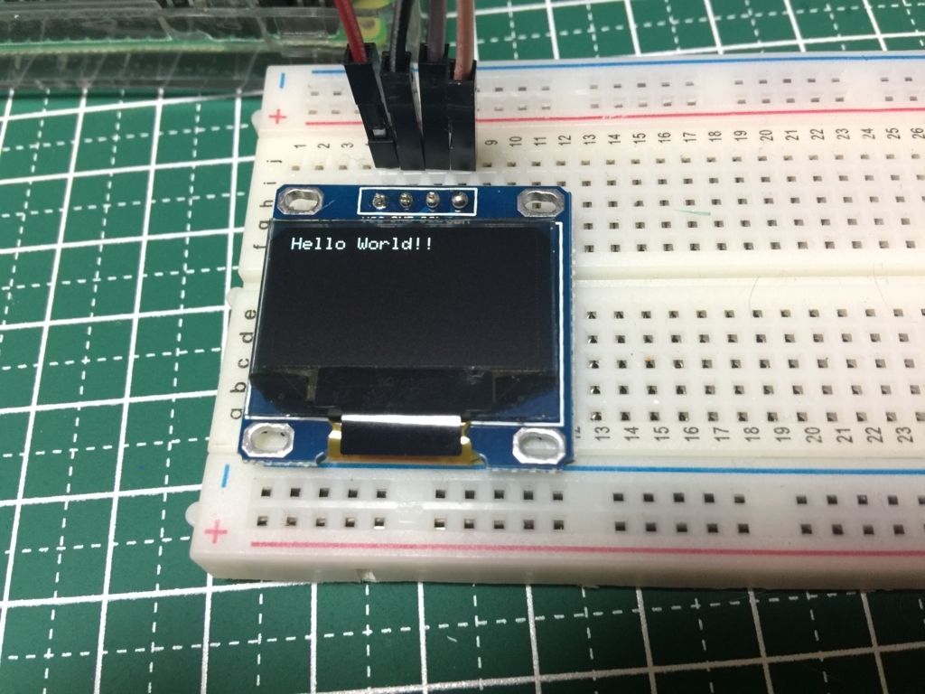
 すると下記のようにディスプレイに文字が表示されます。

f:id:akanuma-hiroaki:20171014221514j:plain:w450

 フォントを大きくしてみます。上記コードの execute メソッドに下記のようにフォントサイズの設定を追加して実行します。

  def execute
    @disp.font_size = 2 # フォントサイズの設定
    @disp.println('Hello World!!')
    @disp.display!
  end

 すると先ほどと比べて縦横が二倍になった大きさで文字が表示されます。

f:id:akanuma-hiroaki:20171014222203j:plain:w450

 次に画像を表示してみます。今回のディスプレイの解像度は 128 x 64 なので、下記のような 128 x 64 のモノクロ画像を用意し、 Raspberry Pi 上に cat.png として配置しておきます。

f:id:akanuma-hiroaki:20171014224726p:plain:w200

 そしてコードは下記のようにしました。 ImageMagick の Image クラスで画像を読み込んで、それを画像表示用メソッドに渡す形になります。

require 'bundler/setup'
require 'SSD1306'

include Magick

class Display

  def initialize
    @disp = SSD1306::Display.new
  end

  def execute
    img = Image.read('/home/pi/display_sample/cat.png').first
    @disp.image(img)
    @disp.display!
  end
end

if $0 == __FILE__
  display = Display.new
  display.execute
end

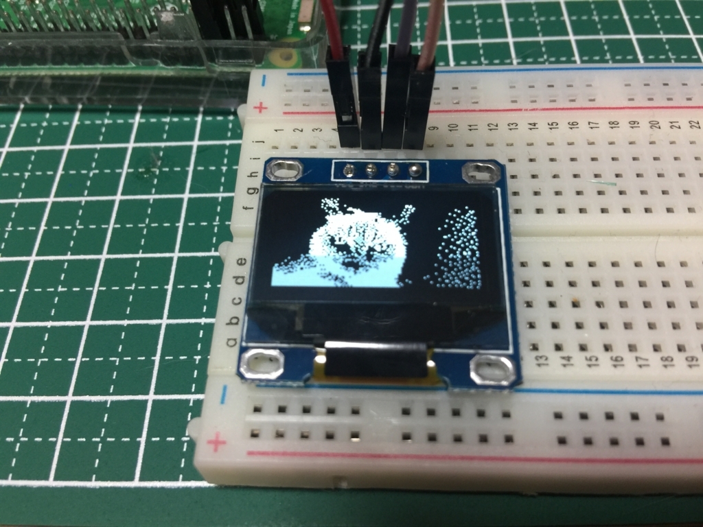
 これを実行すると下記のような感じで画像が表示されます。比較用に元の画像を並べておきます。

f:id:akanuma-hiroaki:20171014224850j:plain:w450f:id:akanuma-hiroaki:20171014224726p:plain

温度計付き時計の実装

 それではここまでの内容を踏まえて時計を表示させてみたいと思います。ついでに温度センサーを組み合わせて温度も一緒に表示します。温度センサーは以前使ったことのある DS18B20 を使います。モジュールの設定方法などについてはこちらの記事をご参照ください。配線は下記のようにしています。

f:id:akanuma-hiroaki:20171019083901p:plain:w300

 まずは温度計のクラスを下記のように実装します。 DS18B20 からの温度データの読み出し方の詳細については先ほどのリンク先の記事をご覧いただくとして、ここでは割愛します。

require 'bundler/setup'

SENSOR_FILE_PATH = '/sys/bus/w1/devices/28-*/w1_slave'.freeze

# For using thermo sensor DS18B20.
class ThermoMeter
  def initialize
    @device_file_name = Dir.glob(SENSOR_FILE_PATH).first
  end

  def read
    sensor_data = File.read(@device_file_name)
    sensor_data.match(/t=(.*$)/)[1].to_f / 1000
  end
end

 次に SSD1306 を使うためのクラスを下記のように実装します。 SSD1306::Display のメソッドをラップした形です。

require 'bundler/setup'
require 'SSD1306'

include Magick

class Display
  def initialize
    @disp = SSD1306::Display.new
  end

  def font_size(size)
    @disp.font_size = size
  end

  def show
    @disp.display!
  end

  def clear
    @disp.clear!
  end

  def println(str)
    @disp.println(str)
  end

  def print(str)
    @disp.print(str)
  end
end

 そして時計を表示するためのクラスを下記のように実装します。やっていることは単純で、ループを回して一秒ごとに前回ループ時の時刻と今回の時刻が分単位で同じかをチェックし、変わっていれば温度データも取得して画面の表示を更新しています。

require 'bundler/setup'
require './display.rb'
require './thermometer.rb'

class Clock
  TIMEZONE     = 'Asia/Tokyo'
  DATE_FORMAT  = '%Y/%m/%d'
  TIME_FORMAT  = '%H:%M'
  DATE_FONT_PX = 2
  TIME_FONT_PX = 4
  TEMP_FONT_PX = 2

  def initialize
    ENV['TZ'] = 'Asia/Tokyo'
    @display = Display.new
    @thermo_meter = ThermoMeter.new
    @time_str_buffer = ''
  end

  def redisplay_time(date_str, time_str)
    @display.clear
    @display.font_size(DATE_FONT_PX)
    @display.println(date_str)
    @display.font_size(TIME_FONT_PX)
    @display.println(time_str)
    @display.font_size(TEMP_FONT_PX)
    @display.println("#{@thermo_meter.read.round(1)} deg.C")
    @display.show
  end

  def start
    begin
      loop do
        sleep(1)

        now = Time.now.localtime

        date_str = now.strftime(DATE_FORMAT)
        time_str = now.strftime(TIME_FORMAT)

        next if @time_str_buffer == time_str

        @time_str_buffer = time_str
        redisplay_time(date_str, time_str)
      end
    rescue => e
      puts e.backtrace.join("\n")
    ensure
      @display.clear
    end
  end
end

if $PROGRAM_NAME == __FILE__
  clock = Clock.new
  clock.start
end

 これを下記のように実行すると、ディスプレイに現在時刻と気温が表示されます。

pi@raspberrypi:~/display_sample $ bundle exec ruby clock.rb

f:id:akanuma-hiroaki:20171019090020j:plain:w450

まとめ

 液晶ディスプレイが使えるようになるとできることの幅も広がりそうですし、デバッグも便利になりそうです。今回は公開されている Gem をそのまま使っただけなので細かい制御まではできていませんが、表示している内容の一部分だけを書き換えたりできるようになると、レイアウトも柔軟にできそうな気がします。

 今回のコードは下記にも公開しました。

github.com

 おまけで画像の表示サンプルに使った画像の元画像を載せておきます。

f:id:akanuma-hiroaki:20171015002714j:plain:w300

BLE Nano + 焦電センサーで人感センサーを作ってみる

 今回は BLE Nano と焦電センサーを使って人感センサーを作ってみました。焦電センサーは人間等が放出する熱エネルギーに変化が生じた時に発生する赤外線を検知するため、人感センサーとして使うことができます。ただし熱エネルギーの「変化」を検知するので、人がいても動かずじっとしている時には検知されませんので、ずっとそこにいることを検知するというよりは、入室や通過等を検知するのに向いているようです。

DAPLink と接続して配線する

 今回使用している焦電センサーは、焦電型赤外線センサー PaPIRs 5m EKMC1601111 です。

akizukidenshi.com

 また、今回下記サイトを参考に BLE Nano と EKMC1601111 の Fritzing パーツを自作してみました。

Fritzingパーツ作成方法 | Home Made Garbage

Fritzing カスタムパーツの作り方 – jumbleat

そして配線図はこちらです。

f:id:akanuma-hiroaki:20171014115114p:plain

 プログラムの書き込みとシリアル接続でのデバック用に DAPLink と BLE Nano を接続しているので、電源も DAPLink から VIN ピンで取り、VDD ピンから LED と焦電センサーに供給しています。 LED は動作確認用で、焦電センサーが人の動きを感知しているときは点灯させます。 EKMC1601111 には 3本のピンがあり、上記配線図では左から VDD, OUT, GND となっていますので、 OUT は抵抗を噛ませて BLE Nano の P0_5 ピンと接続しています。

ソースコード

 今回実装したコードの全文は下記の通りです。以前の照度センサーの時と大体同じで、焦電センサーの値を扱うカスタムサービスを PyroelectricService.h として実装しています。

#ifndef __BLE_PYROELECTRIC_SERVICE_H__
#define __BLE_PYROELECTRIC_SERVICE_H__

class PyroelectricService {
public:
  const static uint16_t PYROELECTRIC_SERVICE_UUID = 0xA000;
  const static uint16_t PYROELECTRIC_VALUE_CHARACTERISTIC_UUID = 0xA001;

  PyroelectricService(BLE &_ble, bool initialValueForPyroelectricCharacteristic) :
    ble(_ble), pyroelectricState(PYROELECTRIC_VALUE_CHARACTERISTIC_UUID, &initialValueForPyroelectricCharacteristic, GattCharacteristic::BLE_GATT_CHAR_PROPERTIES_NOTIFY)
  {
    GattCharacteristic *charTable[] = {&pyroelectricState};
    GattService pyroelectricService(PYROELECTRIC_SERVICE_UUID, charTable, sizeof(charTable) / sizeof(GattCharacteristic *));
    ble.gattServer().addService(pyroelectricService);
  }

  void updatePyroelectricState(bool newState) {
    ble.gattServer().write(pyroelectricState.getValueHandle(), (uint8_t *)&newState, sizeof(bool));
  }

private:
  BLE &ble;
  ReadOnlyGattCharacteristic<bool> pyroelectricState;
};

#endif

 そして main.cpp から PyroelectricSerivce.h を使用しています。

#include "mbed.h"
#include "ble/BLE.h"
#include "PyroelectricService.h"

Serial pc(USBTX, USBRX);
DigitalOut led(P0_4, 0);
AnalogIn pyro(P0_5);

const static char DEVICE_NAME[] = "PyroSample";
static const uint16_t uuid16_list[] = {PyroelectricService::PYROELECTRIC_SERVICE_UUID};

static volatile bool triggerSensorPolling = false;

unsigned short pyroValue;
const int threshold = 500;

bool pyroelectricState;

PyroelectricService *pyroelectricServicePtr;

Ticker ticker;

BLE ble;

void disconnectionCallback(const Gap::DisconnectionCallbackParams_t *params)
{
  BLE::Instance().gap().startAdvertising();
}

void periodicCallback(void)
{
  pyroValue = pyro.read_u16();
  pyroelectricState = pyroValue >= threshold;
  if (pyroelectricState) {
    led = 1;
  } else {
    led = 0;
  }

  triggerSensorPolling = true;
}

void onBleInitError(BLE &ble, ble_error_t error)
{
}

void bleInitComplete(BLE::InitializationCompleteCallbackContext *params)
{
  BLE& ble = params->ble;
  ble_error_t error = params->error;

  if (error != BLE_ERROR_NONE) {
    onBleInitError(ble, error);
    return;
  }

  if (ble.getInstanceID() != BLE::DEFAULT_INSTANCE) {
    return;
  }

  ble.gap().setDeviceName((const uint8_t *) DEVICE_NAME);
  ble.gap().onDisconnection(disconnectionCallback);

  bool initialValueForPyroelectricCharacteristic = false;
  pyroelectricServicePtr = new PyroelectricService(ble, initialValueForPyroelectricCharacteristic);

  ble.gap().accumulateAdvertisingPayload(GapAdvertisingData::BREDR_NOT_SUPPORTED | GapAdvertisingData::LE_GENERAL_DISCOVERABLE);
  ble.gap().accumulateAdvertisingPayload(GapAdvertisingData::COMPLETE_LIST_16BIT_SERVICE_IDS, (uint8_t *)uuid16_list, sizeof(uuid16_list));
  ble.gap().accumulateAdvertisingPayload(GapAdvertisingData::COMPLETE_LOCAL_NAME, (uint8_t *)DEVICE_NAME, sizeof(DEVICE_NAME));
  ble.gap().setAdvertisingType(GapAdvertisingParams::ADV_CONNECTABLE_UNDIRECTED);
  ble.gap().setAdvertisingInterval(1000);
  ble.gap().startAdvertising();
}

int main(void)
{
  pc.printf("Starting BLE_PYROELECTRIC...\r\n");

  ticker.attach(periodicCallback, 1);

  pc.printf("Initializing BLE Controller...\r\n");
  ble.init(bleInitComplete);
  pc.printf("Initialized.\r\n");

  while (ble.hasInitialized() == false) { /* spin loop */ }

  pc.printf("Starting loop...\r\n");
  while(true) {
    if (triggerSensorPolling) {
      triggerSensorPolling = false;
      pc.printf("%d\r\n", pyroelectricState);
      pyroelectricServicePtr->updatePyroelectricState(pyroelectricState);
    } else {
      ble.waitForEvent();
    }
  }
}

 焦電センサーからの出力はアナログ入力として受け取り、入力値が閾値を上回ったかどうかでステータスを切り替えています。

AnalogIn pyro(P0_5);
void periodicCallback(void)
{
  pyroValue = pyro.read_u16();
  pyroelectricState = pyroValue >= threshold;
  if (pyroelectricState) {
    led = 1;
  } else {
    led = 0;
  }

  triggerSensorPolling = true;
}

 最初はデジタル入力として試していたのですが、一度検知して true を返すようになると、その後正しく false に戻らなかったため、アナログ入力の値を使うようにしてみました。 BLE のカスタムサービスで扱う値が bool になったという以外は、基本的には照度センサーを使用した時と同様の構成です。

動作確認

 ではプログラムをコンパイルして書き込んで、動作確認してみます。

[vagrant@localhost BLE_PYROELECTRIC]$ mbed compile
Building project BLE_PYROELECTRIC (RBLAB_BLENANO, GCC_ARM)
Scan: .
Scan: mbed
Scan: env
Compile [100.0%]: main.cpp
Link: BLE_PYROELECTRIC
Elf2Bin: BLE_PYROELECTRIC
+-----------+-------+-------+------+
| Module    | .text | .data | .bss |
+-----------+-------+-------+------+
| Fill      |   127 |     3 |   47 |
| Misc      | 41520 |   141 | 1649 |
| Subtotals | 41647 |   144 | 1696 |
+-----------+-------+-------+------+
Allocated Heap: 2256 bytes
Allocated Stack: 2048 bytes
Total Static RAM memory (data + bss): 1840 bytes
Total RAM memory (data + bss + heap + stack): 6144 bytes
Total Flash memory (text + data + misc): 41791 bytes

Image: ./BUILD/RBLAB_BLENANO/GCC_ARM/BLE_PYROELECTRIC.hex
[vagrant@localhost BLE_PYROELECTRIC]$ 
[vagrant@localhost BLE_PYROELECTRIC]$ cp ./BUILD/RBLAB_BLENANO/GCC_ARM/BLE_PYROELECTRIC.hex /run/media/vagrant/DAPLINK/
[vagrant@localhost BLE_PYROELECTRIC]$ 

 するとシリアル接続していると下記のように、人の動きを検知しているときは 1 を、検知していないときは 0 を出力します。

Starting BLE_PYROELECTRIC...
Initializing BLE Controller...
Initialized.
Starting loop...
0
0
0
0
0
0
0
0
1
1
1
1
1
0
0

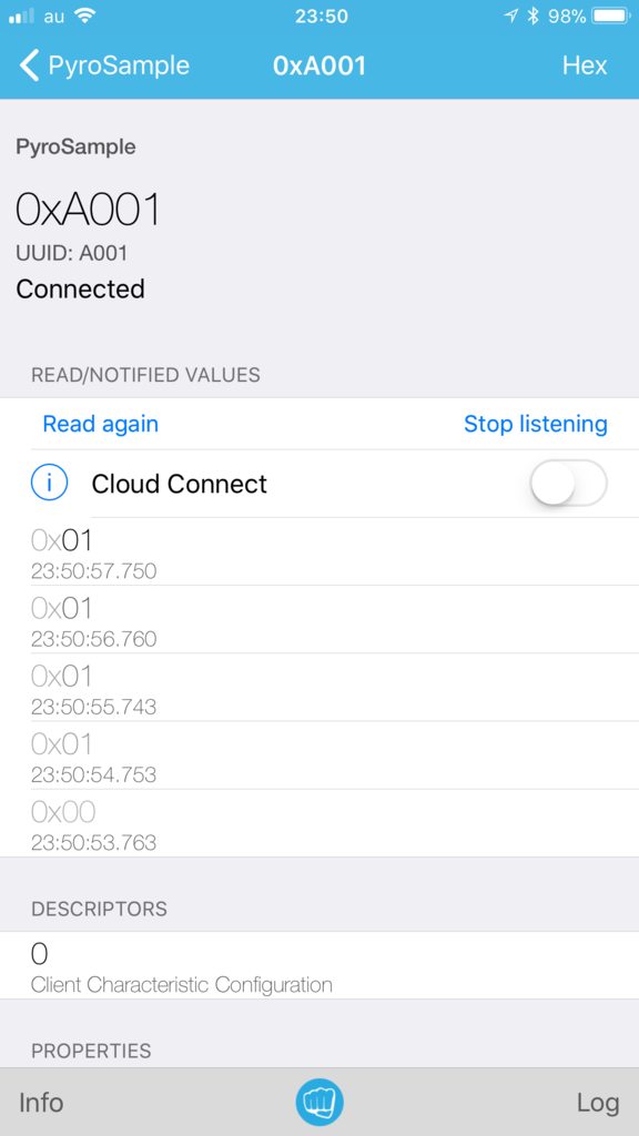
 また、 LightBlue でも下記のように Peripheral のリストに PyroSample が表示され、接続して Notification を Listen すると値が更新されていくのが確認できます。

f:id:akanuma-hiroaki:20171009235322p:plain:w300 f:id:akanuma-hiroaki:20171009235347p:plain:w300

ボタン電池で動かす

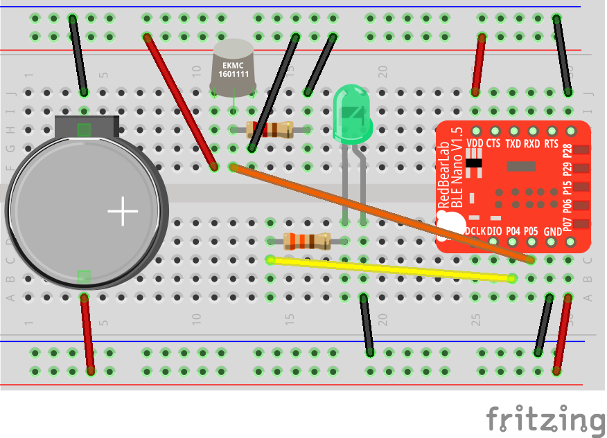
 動作確認ができたので、実際にセンサーとして使う場合を想定して、DAPLink から切り離してボタン電池で動かしてみます。配線は下記のようにしました。

f:id:akanuma-hiroaki:20171014133706p:plain

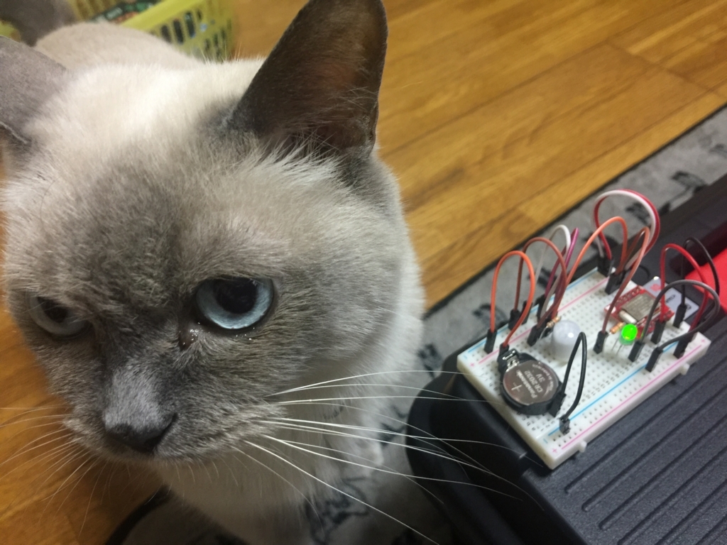
 CR2032 のボタン電池ホルダーを配置し、+側から BLE Nano の VIN ピンに給電しています。ボタン電池をはめればすぐに起動して動き始めます。ちなみに「人感」センサーと言ってますが猫でもちゃんと検知します。

[f:id:akanuma-hiroaki:20171014135212j:plain:450]

まとめ

 冒頭でも書きましたが、焦電センサーは動きを検知することになるため、そこに人間や動物がいても、ほとんど動いてなければ検知されません。猫が昼寝スポットにいるかどうかを検知するものでも作ってみようかと思ってたのですが、焦電センサーだとその用途にはマッチしないようです。

f:id:akanuma-hiroaki:20171014140347j:plain:w300:left

 また、動作確認をしていると、実際はセンサー前で動き続けていても時々検知結果が false になるので、在室検知のようなことをするとしたら、状態の管理としてはある程度 false の時間が続いたら false と判定するのが良さそうです。

Raspberry Pi とモーターを繋げて Ruby で動かす

 今までは Raspberry Pi と他のセンサー類を組み合わせてセンサー値を読み取り、データとして使える形にはしていましたが、ハードウェアのアウトプットとしては LED を光らせるぐらいでした。今回はモーターを動かすことに挑戦してみたいと思います。

電池ボックスとモーターの配線準備

 今回は下記のモーターと電池ボックスを使用します。

akizukidenshi.com

akizukidenshi.com

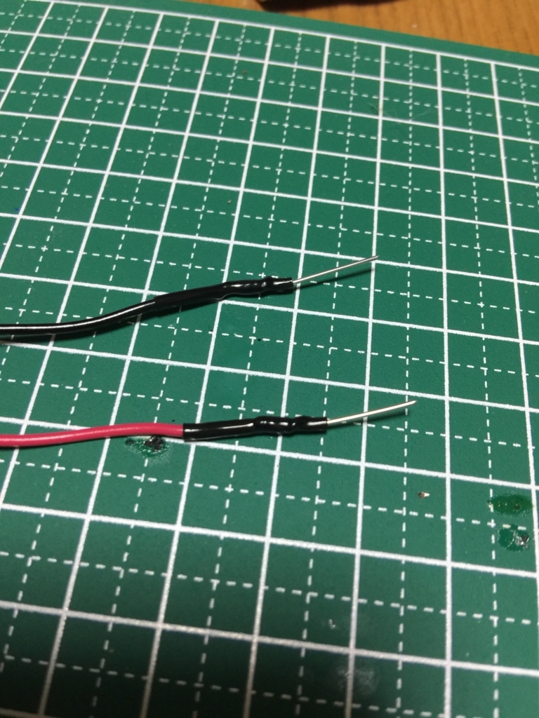
 いずれもリード線はついていますが、そのままではブレッドボードにさすには不便なので、下記サイトを参考にリード線を加工しました。

ブレッドボードで電子回路の実験をするために乾電池ホルダーのリード線をジャンパワイヤのように端子化するmatsumotoyoshio.wordpress.com

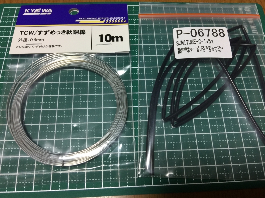
 加工に使った材料は下記の二つです。

f:id:akanuma-hiroaki:20171001150412j:plain:w450

 最終的に下記のようにリード線の先端にピンがついた形になりました。

f:id:akanuma-hiroaki:20170930084942j:plain:w300

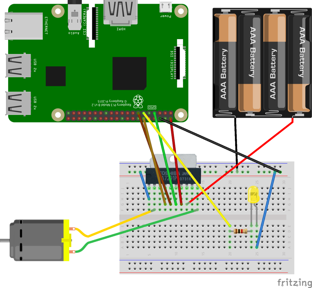
ブレッドボードで配線する

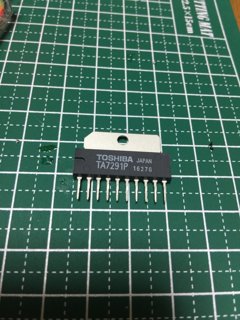
 今回モーターを回すためにさらに必要なものとして、下記のモータードライバ(TA7291P)を使用しました。

f:id:akanuma-hiroaki:20170930085035j:plain:w300

 これらを動作確認用の LED と組み合わせて、下記の図のように配線します。ちなみに TA7291P の Fritzing 用の画像は下記サイトのものを使用させていただきました。

無料ダウンロード:Fritzing 部品一覧

f:id:akanuma-hiroaki:20171001203824p:plain

 モータードライバの各PINは下記のように接続しています。

  1. GND
  2. モーターの片方の端子
  3. 未接続
  4. Vref. Raspberry Pi の 18番PIN
  5. IN1. Raspberry pi の 27番PIN
  6. IN2. Raspberry Pi の 4番PIN
  7. Raspberry Pi の 5V 電源出力
  8. 電池ボックスの+側
  9. 未接続
  10. モーターのもう一方の端子

 TA7291P の4番PINはモーターへの出力調整用なので、電圧を調整できるように Raspberry Pi の PWM対応ピンに接続しています。

モーターを回すサンプルコード

 Ruby で GPIO を操作するために pi_piper を使っていますが、 PWM を使う場合は pi_piper のPwmクラスを使用します。

http://www.rubydoc.info/github/jwhitehorn/pi_piper/PiPiper/Pwm

 まずはサンプルコードの全体を掲載します。

require 'bundler/setup'
require 'pi_piper'

PIN_VREF = 18
PIN_IN_1 = 27
PIN_IN_2 =  4
PIN_LED  = 17 

class MotorSample
  def initialize
    puts 'Initializing MotorSample...'
    @pin_led  = PiPiper::Pin.new(pin: PIN_LED,  direction: :out)
    @pin_in_1 = PiPiper::Pin.new(pin: PIN_IN_1, direction: :out)
    @pin_in_2 = PiPiper::Pin.new(pin: PIN_IN_2, direction: :out)
    @pin_vref = PiPiper::Pwm.new(pin: PIN_VREF)
    @pin_vref.value = 0
  end

  def stop_motor
    puts 'Stopping.'
    @pin_led.off
    @pin_in_1.off
    @pin_in_2.off
    sleep 1
  end

  def toggle_led(i)
    i % 2 == 0 ? @pin_led.on : @pin_led.off
  end

  def speeding_up
    puts 'Speeding Up...'
    0.step(1.0, 0.1) do |v|
      toggle_led((v * 10).to_i)
      @pin_vref.value = v
      sleep 2
    end
  end

  def slowing_down
    puts 'Slowing Down...'
    1.0.step(0, -0.1) do |v|
      toggle_led((v * 10).to_i)
      @pin_vref.value = v
      sleep 2
    end
  end

  def execute
    puts 'Rolling Forward.'
    @pin_in_1.on
    @pin_in_2.off
    speeding_up
    slowing_down

    stop_motor

    puts 'Rolling Backward.'
    @pin_in_1.off
    @pin_in_2.on
    speeding_up
    slowing_down
  end
end

if $0 == __FILE__
  motor_sample = MotorSample.new
  motor_sample.execute
end

 上記のサンプルコードを動かすと、モーターが順方向へ回転し始めて徐々に速度を上げ、最高速度に到達すると徐々に速度を下げていきます。そして今度は逆方向へ同様のことを行って終了します。

 ON/OFF の切り替えで良いピンは PiPiper::Pin を new していますが、 PWM を使いたいピンについては PiPiper::Pwm を new しています。

  def initialize
    puts 'Initializing MotorSample...'
    @pin_led  = PiPiper::Pin.new(pin: PIN_LED,  direction: :out)
    @pin_in_1 = PiPiper::Pin.new(pin: PIN_IN_1, direction: :out)
    @pin_in_2 = PiPiper::Pin.new(pin: PIN_IN_2, direction: :out)
    @pin_vref = PiPiper::Pwm.new(pin: PIN_VREF)
    @pin_vref.value = 0
  end

 TA7291P ではモーターの ON/OFF/回転方向 の切り替えは IN1 と IN2 の ON/OFF の組み合わせて決定します。

  • IN1: OFF IN2: OFF => 停止
  • IN1: ON IN2: OFF => 順方向へ回転
  • IN1: OFF IN2: ON => 逆方向へ回転

 例えば順方向へ回転させるには下記のように指定しています。

    @pin_in_1.on
    @pin_in_2.off

 PWM を使用しているピンについてはその値を 0 〜 1.0 で指定することで出力を調整できます。今回は例えば下記のように徐々に値を増加させ、モーターの回転速度を上げていったりしています。

  def speeding_up
    puts 'Speeding Up...'
    0.step(1.0, 0.1) do |v|
      toggle_led((v * 10).to_i)
      @pin_vref.value = v
      sleep 2
    end
  end

Beacon の電波強度に応じてモーターの回転速度を調節する

 指定した速度で動かすだけでは面白くないので、今度は BLE と組み合わせ、 Beacon の電波強度(RSSI)に応じてモーターの回転速度を変化させてみたいと思います。

 まずはモーターの動作をまとめた Motor クラスを作成します。内容としては単純に各ピンの初期化と、 ON/OFF、速度調節の値を設定する機能をまとめたものです。

require 'bundler/setup'
require 'pi_piper'

class Motor
  def initialize(pin_vref, pin_in_1, pin_in_2)
    @pin_in_1 = PiPiper::Pin.new(pin: pin_in_1, direction: :out)
    @pin_in_2 = PiPiper::Pin.new(pin: pin_in_2, direction: :out)
    @pin_vref = PiPiper::Pwm.new(pin: pin_vref)
    @pin_vref.value = 0
  end

  def stop
    @pin_in_1.off
    @pin_in_2.off
  end

  def forward
    @pin_in_1.on
    @pin_in_2.off
  end

  def backward
    @pin_in_1.off
    @pin_in_2.on
  end

  def adjust(value)
    @pin_vref.value = value
  end
end

 BLE で Beacon の Advertisement を受け取って Motor を操作するコードは下記のようにしました。今回は Beacon として以前にも使ったことのある、 Texas Instruments の SensorTag を使用しています。

require 'bundler/setup'
require 'dbus'
require './motor.rb'

class MotorTest
  SERVICE_NAME = 'org.bluez'
  SERVICE_PATH = '/org/bluez'
  ADAPTER = 'hci0'
  DEVICE_IF = 'org.bluez.Device1'
  DBUS_PROPERTIES_IF = 'org.freedesktop.DBus.Properties'
  PROPERTIES_CHANGED_SIGNAL = 'PropertiesChanged'
  DEVICE_NAME = 'CC2650'

  PIN_VREF = 18
  PIN_IN_1 = 27
  PIN_IN_2 =  4
  PIN_LED  = 17

  def initialize
    @bus = DBus::system_bus
    @bluez = @bus.service(SERVICE_NAME)

    @adapter = @bluez.object("#{SERVICE_PATH}/#{ADAPTER}")
    @adapter.introspect

    @motor = Motor.new(PIN_VREF, PIN_IN_1, PIN_IN_2)
    @motor.forward

    @led = PiPiper::Pin.new(pin: PIN_LED, direction: :out)
  end

  def execute
    @adapter.SetDiscoveryFilter({'Transport' => 'le'})
    @adapter.StartDiscovery

    @led.on

    target_device = nil

    while(target_device.nil?)
      @adapter.introspect
      @adapter.subnodes.each do |node|
        device = @bluez.object("#{SERVICE_PATH}/#{ADAPTER}/#{node}")
        device.introspect

        next unless device.respond_to?(:GetAll)

        properties = device.GetAll(DEVICE_IF).first
        name = properties['Name']
        rssi = properties['RSSI']

        next if name.nil?
        next unless name.downcase.include?(DEVICE_NAME.downcase)

        target_device = device
        break
      end

      sleep(0.1)
    end

    target_device.default_iface = DBUS_PROPERTIES_IF
    target_device.on_signal(PROPERTIES_CHANGED_SIGNAL) do |_, v|
      rssi = v['RSSI']
      vref_value = [[(100 + rssi).to_f / 100, 1.0].min, 0].max
      puts "RSSI: #{rssi} VREF: #{vref_value}"
      @motor.forward
      @motor.adjust(vref_value)
    end

    main = DBus::Main.new
    main << @bus

    main.run
  end
end

if $0 == __FILE__
  motor_test = MotorTest.new
  motor_test.execute
end

 BLE の操作については DBus と BlueZ を使い、 initialize で Bluetooth アダプタの初期化と Motor クラスの初期化を行っています。

  def initialize
    @bus = DBus::system_bus
    @bluez = @bus.service(SERVICE_NAME)

    @adapter = @bluez.object("#{SERVICE_PATH}/#{ADAPTER}")
    @adapter.introspect

    @motor = Motor.new(PIN_VREF, PIN_IN_1, PIN_IN_2)
    @motor.forward

    @led = PiPiper::Pin.new(pin: PIN_LED, direction: :out)
  end

 execute メソッドの中でBLEデバイスのスキャンを行っていますが、検索対象を絞るために SetDiscoveryFilter で BLE デバイスに限定しています。

    @adapter.SetDiscoveryFilter({'Transport' => 'le'})
    @adapter.StartDiscovery

 RSSI が変わると PropertiesChanged シグナルが送られてくるので、シグナルを受け取った場合にモーターの速度を変更するようにしています。 PWM ピンに設定できる値は 0 〜 1.0 なので、その範囲を出ないようにしています。今回は RSSI を厳密に取り扱うことが目的ではないので、上限と下限を超える場合は超える分をカットしている形です。

    target_device.default_iface = DBUS_PROPERTIES_IF
    target_device.on_signal(PROPERTIES_CHANGED_SIGNAL) do |_, v|
      rssi = v['RSSI']
      vref_value = [[(100 + rssi).to_f / 100, 1.0].min, 0].max
      puts "RSSI: #{rssi} VREF: #{vref_value}"
      @motor.forward
      @motor.adjust(vref_value)
    end

 このコードを動かすと、 SensorTag を Raspberry Pi に近づけるとモーターの回転速度が上がり、遠ざけると回転速度が下がります。SensorTag を動かしてからシグナルが送られるまでにタイムラグがあるのですが、とりあえずイメージした感じにはなっているので、今後調べられそうであればシグナル発行のタイミングも調べてみたいと思います。

まとめ

 今回初めて外部電源(電池ボックス)を使ってモーターを動かすことに挑戦してみました。実は途中で一度、横に置いておいた電池ボックスのリード線がいつの間にかショートして、電池ボックスを一つ焦がしてダメにしてしまい、やっぱり電気は怖いなぁと改めて思ったのですが、モーターなどを動かすことができると色々とやれる幅も広がって楽しいですね。モータードライバなどは物によって使い方が違うので、データシートなどから読み解くのは少し大変ですが、色々触って試してみたいと思います。

BLE Nano を光センサー CdS と組み合わせる

 前回までは BLE Nano をそのまま USB のライター DAPLink にさして使っていましたが、このままだと他のセンサー類と組み合わせることができないので、 BLE Nano をブレッドボードにさして使ってみます。まずは BLE Nano をブレッドボードにさして動作させられることを確認し、その後実際のセンサーと組み合わせて値を取得してみます。

ブレッドボードで配線

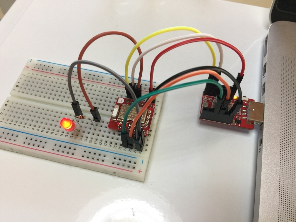
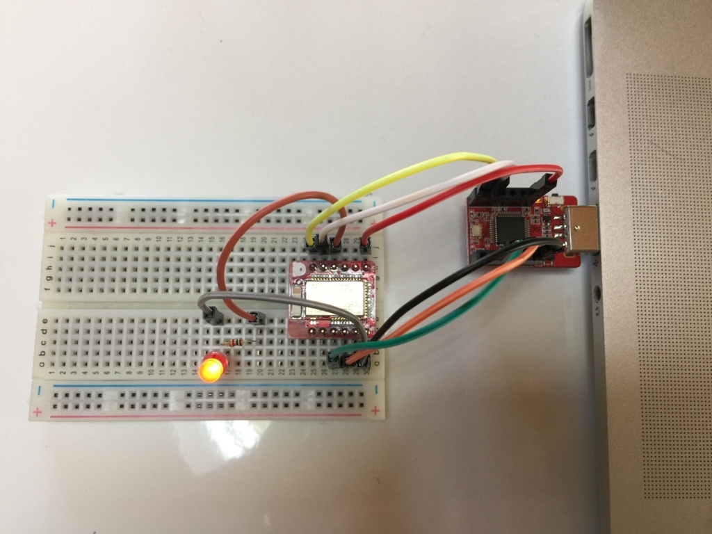
 写真だとちょっと分かりづらいですが、今回は下記のように配線しました。基本的には BLE Nano をブレッドボードにさして、DAPLink の対応するピンとオス-オスのジャンパーワイヤーで接続しています。

f:id:akanuma-hiroaki:20170918144703j:plain:w450 f:id:akanuma-hiroaki:20170918144714j:plain:w450

 今回は下記のピンを接続しました。

  • SWCLK
  • SWDIO
  • VIN
  • GND
  • TXD
  • RXD

 シリアル接続でのデバッグ等を行わなければ TXD, RXD は不要かもしれません。

 また、今回は LED と抵抗を接続して、前回のプログラムで BLE Nano のオンボードLEDを点滅させていたところを、ブレッドボード上の LED を点滅させてみます。 BLE Nano の P0_4 ピンから 1kΩ の抵抗を経由して LED のアノード側に接続し、カソード側と BLE Nano の GND ピンに接続しています。

ソースコードを変更してコンパイル&実行

 前回実装したコードの LED のピンの指定を下記のように変更します。

DigitalOut led(LED1, 0);
 ↓
DigitalOut led(P0_4, 0);

 そして mbed compile して hex ファイルを BLE Nano に転送すると、ブレッドボード上の LED が点滅を開始し、 LightBlue などでは前回同様にデバイスが検知され、 Characteristic の値が確認できます。

ボタン電池で動かす

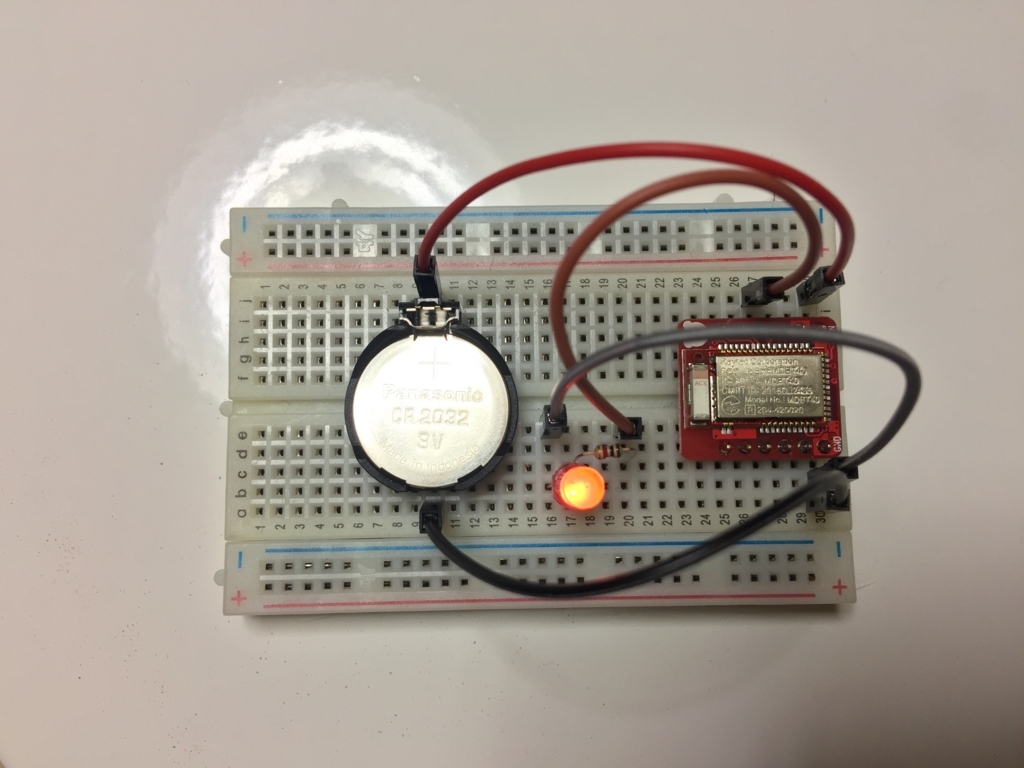
 開発・デバッグ時は DAPLink に接続しているので電源もそこから取っていますが、実際に何か BLE デバイスを作成した時には単体で動くようにする必要があるので、ボタン電池で動かしてみます。配線は下記の写真のようにしました。

f:id:akanuma-hiroaki:20170923015011j:plain:w450

 DAPLink の VIN と GND にさしていたピンをそれぞれボタン電池ホルダーの + 側と - 側に繋いで、それ以外のコードを取り外しています。今回はスイッチなどはつけてないので、ボタン電池をつけるとすぐにプログラムが動き始めます。 LightBlue などで接続してみると今まで同様に動作していることが確認できます。

実際のセンサーと組み合わせる

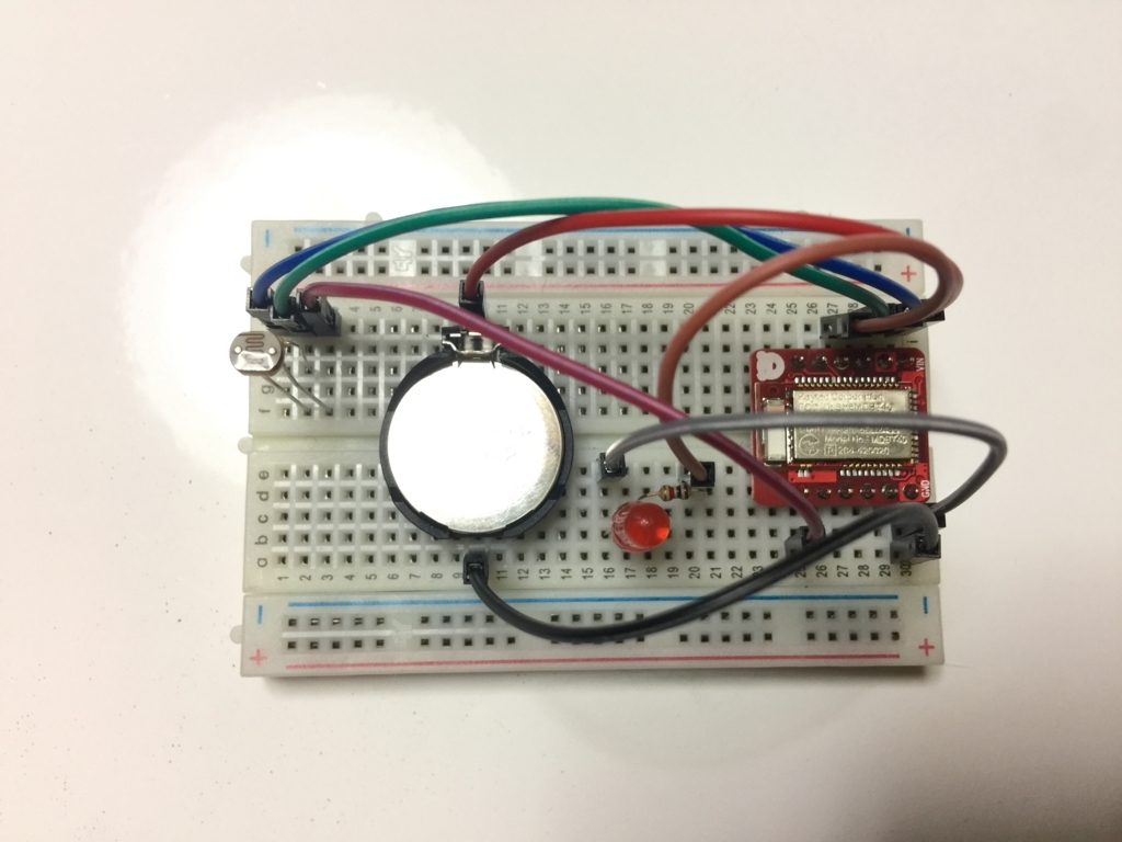
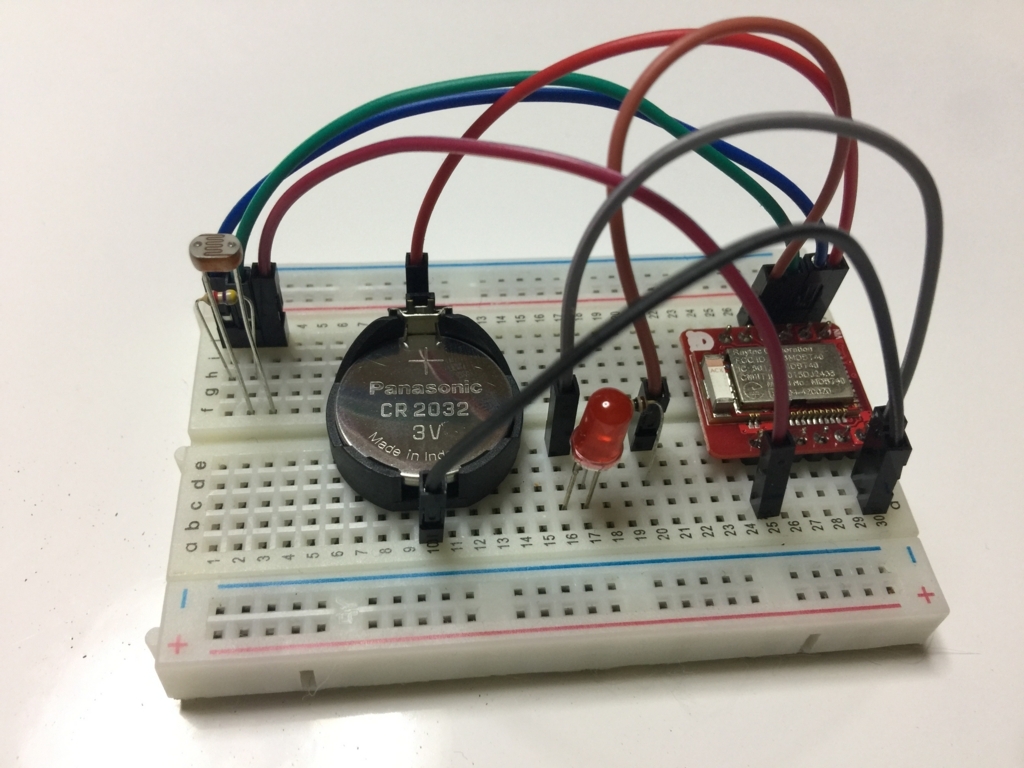
 先ほどまではダミーの値をセンサー値として使用していましたが、今度は実際のセンサーと組み合わせてみます。今回は下記の光センサー CdSセルを使用してみました。

www.aitendo.com

 これを 4.7kΩの抵抗と組み合わせて下記の写真のように配線しました。

f:id:akanuma-hiroaki:20170923015435j:plain:w450 f:id:akanuma-hiroaki:20170923015458j:plain:w450

 コードも実際のセンサー値を使用するように変更します。 main.cpp は下記のようにしました。

#include "mbed.h"
#include "ble/BLE.h"
#include "LuxService.h"

Serial pc(USBTX, USBRX);
DigitalOut led(P0_4, 0);
AnalogIn cds(P0_5);

const static char DEVICE_NAME[] = "LUXSample";
static const uint16_t uuid16_list[] = {LuxService::LUX_SERVICE_UUID};

static volatile bool triggerSensorPolling = false;

unsigned short luxValue;
const int threshold = 500;

LuxService *luxServicePtr;

Ticker ticker;

BLE ble;

void disconnectionCallback(const Gap::DisconnectionCallbackParams_t *params)
{
  BLE::Instance().gap().startAdvertising();
}

void periodicCallback(void)
{
  luxValue = cds.read_u16();
  if (luxValue >= threshold) {
    led = 0;
  } else {
    led = 1;
  }

  triggerSensorPolling = true;
}

void onBleInitError(BLE &ble, ble_error_t error)
{
}

void bleInitComplete(BLE::InitializationCompleteCallbackContext *params)
{
  BLE& ble = params->ble;
  ble_error_t error = params->error;

  if (error != BLE_ERROR_NONE) {
    onBleInitError(ble, error);
    return;
  }

  if (ble.getInstanceID() != BLE::DEFAULT_INSTANCE) {
    return;
  }

  ble.gap().setDeviceName((const uint8_t *) DEVICE_NAME);
  ble.gap().onDisconnection(disconnectionCallback);

  uint16_t initialValueForLUXCharacteristic = 100;
  luxServicePtr = new LuxService(ble, initialValueForLUXCharacteristic);

  ble.gap().accumulateAdvertisingPayload(GapAdvertisingData::BREDR_NOT_SUPPORTED | GapAdvertisingData::LE_GENERAL_DISCOVERABLE);
  ble.gap().accumulateAdvertisingPayload(GapAdvertisingData::COMPLETE_LIST_16BIT_SERVICE_IDS, (uint8_t *)uuid16_list, sizeof(uuid16_list));
  ble.gap().accumulateAdvertisingPayload(GapAdvertisingData::COMPLETE_LOCAL_NAME, (uint8_t *)DEVICE_NAME, sizeof(DEVICE_NAME));
  ble.gap().setAdvertisingType(GapAdvertisingParams::ADV_CONNECTABLE_UNDIRECTED);
  ble.gap().setAdvertisingInterval(1000);
  ble.gap().startAdvertising();
}

int main(void)
{
  pc.baud(115200);
  pc.printf("Starting BLE_LUX Sample...\r\n");

  ticker.attach(periodicCallback, 1);

  pc.printf("Initializing BLE Controller...\r\n");
  ble.init(bleInitComplete);
  pc.printf("Initialized.\r\n");

  while (ble.hasInitialized() == false) { /* spin loop */ }

  pc.printf("Starting loop...\r\n");
  while (true) {
    if (triggerSensorPolling && ble.getGapState().connected) {
      triggerSensorPolling = false;
      pc.printf("%u\r\n", luxValue);
      luxServicePtr->updateLuxValue(luxValue);
    } else {
      ble.waitForEvent();
    }
  }
}

 今までダミーの値を生成していた部分を削除し、実際のセンサーデータを読み出す処理を追加しています。 CdSセルからのデータはアナログ入力として受け取ります。また、今までは一秒間隔で点滅させていたLEDを、センサーデータが閾値より小さかったら(暗かったら)点灯し、大きかったら(明るかったら)消すという処理にしています。

void periodicCallback(void)
{
  luxValue = (cds.read_u16() & 0xffff);
  if (luxValue >= threshold) {
    led = 0;
  } else {
    led = 1;
  }

  triggerSensorPolling = true;
}

 LuxService.h の方も全体を掲載しておきますが、前回との変更は受け取るセンサー値の型を unsigned short に変更しただけです。

#ifndef __BLE_LUX_SERVICE_H__
#define __BLE_LUX_SERVICE_H__

class LuxService {
public:
  const static uint16_t LUX_SERVICE_UUID = 0xA000;
  const static uint16_t LUX_VALUE_CHARACTERISTIC_UUID = 0xA001;

  LuxService(BLE &_ble, uint16_t initialValueForLUXCharacteristic) :
    ble(_ble), luxValue(LUX_VALUE_CHARACTERISTIC_UUID, &initialValueForLUXCharacteristic, GattCharacteristic::BLE_GATT_CHAR_PROPERTIES_NOTIFY)
  {
    GattCharacteristic *charTable[] = {&luxValue};
    GattService luxService(LUX_SERVICE_UUID, charTable, sizeof(charTable) / sizeof(GattCharacteristic *));
    ble.gattServer().addService(luxService);
  }

  void updateLuxValue(unsigned short newValue) {
    ble.gattServer().write(luxValue.getValueHandle(), (uint8_t *)&newValue, sizeof(bool));
  }

private:
  BLE &ble;
  ReadOnlyGattCharacteristic<uint16_t> luxValue;
};

#endif

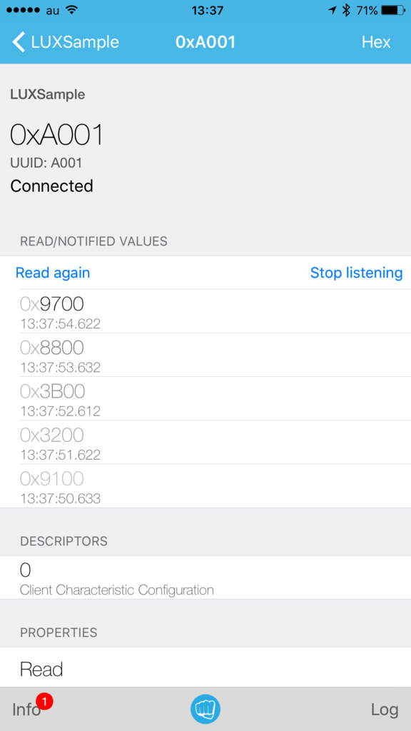
 これで実際のセンサーの計測値をBLEで受け取ることができるようになります。 LightBlue で見てみると下記のように値が取得できます。

f:id:akanuma-hiroaki:20170923134018p:plain:w300

まとめ

 BLE Nano とボタン電池を使うことで簡単にワイヤレスで動作するデバイスが試作できました。どんなセンサーと組み合わせて何をするかはアイディア次第だと思いますので、日常的に役に立ちそうなものを考えてプロトタイプを作ってみたいと思います。

 ちなみに BLE Nano は日本でも V2 が発売されましたね。スペックも上がってるようですし、 DAPLink のバージョンも 1.0 から 1.5 に上がっているようです。DAPLink 1.0 でも BLE Nano V2 が使えるのかなどは気になるところです。

mag.switch-science.com

BLE Nano で Advertisement & カスタムサービス実装

 前回はとりあえずサンプルコードで BLE Nano を iBeacon として動かしましたが、今回は Peripheral として Advertisement を送信する例と、カスタムサービスを定義して Central との通信を行う例を実装してみたいと思います。

Advertisement 送信

 まずは Advertisement に独自の情報を載せて送信してみます。下記サンプルコードをベースにしています。

BLE_GAP_Example - a mercurial repository | Mbed

 ただ上記サンプルを mbed import でインポートしてビルドしたところエラーになってしまったので、新規にプロジェクトを作って実装してみることにしました。

 まずは mbed new でプロジェクトを作成します。デフォルトだと mbed os 5 向けとして作成されますが、 BLE Nano では mbed os 5 に対応していないようなので、 mbed os 2 向けとして作成するために、 --mbedlib オプションをつけて作成します。

[vagrant@localhost vagrant]$ mbed new BLE_GAP_EXAMPLE --mbedlib                                                       
[mbed] Creating new program "BLE_GAP_EXAMPLE" (git)                                                                   
[mbed] Adding library "mbed" from "https://mbed.org/users/mbed_official/code/mbed/builds" at latest revision in the current branch                                                                                                          
[mbed] Updating reference "mbed" -> "https://mbed.org/users/mbed_official/code/mbed/builds/tip"                       
[mbed] Couldn't find build tools in your program. Downloading the mbed 2.0 SDK tools...                               
[vagrant@localhost vagrant]$ 
[vagrant@localhost vagrant]$ cd BLE_GAP_EXAMPLE/
[vagrant@localhost BLE_GAP_EXAMPLE]$            
[vagrant@localhost BLE_GAP_EXAMPLE]$ ls         
mbed  mbed.bld  mbed_settings.py                

 とりあえず toolchain と target を指定しておきます。

[vagrant@localhost BLE_GAP_EXAMPLE]$ mbed detect                                     
                                                                                     
[mbed] Detected RBLAB_BLENANO, port /dev/ttyACM0, mounted /run/media/vagrant/DAPLINK 
[mbed] Supported toolchains for RBLAB_BLENANO                                        
+--------+-----------+-----------+-----+---------+-----+                             
| Target | mbed OS 2 | mbed OS 5 | ARM | GCC_ARM | IAR |                             
+--------+-----------+-----------+-----+---------+-----+                             
+--------+-----------+-----------+-----+---------+-----+                             
Supported targets: 0                                                                 
                                                                                     
[vagrant@localhost BLE_GAP_EXAMPLE]$                                                 
[vagrant@localhost BLE_GAP_EXAMPLE]$ mbed toolchain GCC_ARM                          
[mbed] GCC_ARM now set as default toolchain in program "BLE_GAP_EXAMPLE"             
[vagrant@localhost BLE_GAP_EXAMPLE]$ mbed target RBLAB_BLENANO                       
[mbed] RBLAB_BLENANO now set as default target in program "BLE_GAP_EXAMPLE"          

 ライブラリを更新します。

[vagrant@localhost BLE_GAP_EXAMPLE]$ mbed deploy
[mbed] Updating library "mbed" to branch tip
[mbed] Downloading library build "675da3299148" (might take a minute)
[mbed] Unpacking library build "675da3299148" in "/vagrant/BLE_GAP_EXAMPLE/mbed"
[mbed] Updating the mbed 2.0 SDK tools...

 BLE の Firmware 開発をするには mbed の BLE API が必要なので、 mbed add でライブラリを追加します。

[vagrant@localhost BLE_GAP_EXAMPLE]$ mbed add http://mbed.org/teams/Bluetooth-Low-Energy/code/BLE_API/
[mbed] Adding library "BLE_API" from "https://mbed.org/teams/Bluetooth-Low-Energy/code/BLE_API" at latest revision in the current branch
[mbed] Updating reference "BLE_API" -> "https://mbed.org/teams/Bluetooth-Low-Energy/code/BLE_API/#65474dc93927"

 nRF51822 のライブラリも必要なので mbed add しておきます。

[vagrant@localhost BLE_GAP_EXAMPLE]$ mbed add https://mbed.org/teams/Nordic-Semiconductor/code/nRF51822/
[mbed] Adding library "nRF51822" from "https://mbed.org/teams/Nordic-Semiconductor/code/nRF51822" at latest revision in the current branch
[mbed] Updating reference "nRF51822" -> "https://mbed.org/teams/Nordic-Semiconductor/code/nRF51822/#c90ae1400bf2"

 そして main.cpp はサンプルコードを参考に下記のように実装します。

#include "mbed.h"
#include "ble/BLE.h"

BLE ble;

const static char DEVICE_NAME[] = "SampleDevice";
const static uint8_t AdvData[] = {"SampleAdvertisement"};

void disconnectionCallback(const Gap::DisconnectionCallbackParams_t *params)
{
  BLE::Instance().gap().startAdvertising();
}

void onBleInitError(BLE &ble, ble_error_t error)
{
  (void) ble;
  (void) error;
}

void bleInitComplete(BLE::InitializationCompleteCallbackContext *params)
{
  BLE &ble          = params->ble;
  ble_error_t error = params->error;

  if (error != BLE_ERROR_NONE) {
    onBleInitError(ble, error);
    return;
  }

  if (ble.getInstanceID() != BLE::DEFAULT_INSTANCE) {
    return;
  }

  ble.gap().setDeviceName((const uint8_t *) DEVICE_NAME);
  ble.gap().onDisconnection(disconnectionCallback);

  ble.gap().accumulateAdvertisingPayload(GapAdvertisingData::BREDR_NOT_SUPPORTED | GapAdvertisingData::LE_GENERAL_DISCOVERABLE);
  ble.gap().setAdvertisingType(GapAdvertisingParams::ADV_CONNECTABLE_UNDIRECTED);

  ble.gap().accumulateAdvertisingPayload(GapAdvertisingData::MANUFACTURER_SPECIFIC_DATA, AdvData, sizeof(AdvData));
  ble.gap().accumulateAdvertisingPayload(GapAdvertisingData::COMPLETE_LOCAL_NAME, (uint8_t *) DEVICE_NAME, sizeof(DEVICE_NAME));

  ble.gap().setAdvertisingInterval(100);
  ble.gap().startAdvertising();
}

int main(void)
{
  ble.init(bleInitComplete);

  while (true) {
    ble.waitForEvent();
  }
}

 今回独自のデータとして使用するのは下記のデバイス名とアドバタイズデータです。

const static char DEVICE_NAME[] = "SampleDevice";
const static uint8_t AdvData[] = {"SampleAdvertisement"};

 bleInitComplete() の中で上記データを Advertisement に設定しています。

  ble.gap().accumulateAdvertisingPayload(GapAdvertisingData::MANUFACTURER_SPECIFIC_DATA, AdvData, sizeof(AdvData));
  ble.gap().accumulateAdvertisingPayload(GapAdvertisingData::COMPLETE_LOCAL_NAME, (uint8_t *) DEVICE_NAME, sizeof(DEVICE_NAME));

 これをコンパイルして BLE Nano にコピーします。

[vagrant@localhost BLE_GAP_EXAMPLE]$ mbed compile
Building project BLE_GAP_EXAMPLE (RBLAB_BLENANO, GCC_ARM)
Scan: .
Scan: env
Scan: mbed
Compile [100.0%]: main.cpp
Link: BLE_GAP_EXAMPLE
Elf2Bin: BLE_GAP_EXAMPLE
+-----------+-------+-------+------+
| Module    | .text | .data | .bss |
+-----------+-------+-------+------+
| Fill      |   112 |     3 |   31 |
| Misc      | 33115 |   141 | 1189 |
| Subtotals | 33227 |   144 | 1220 |
+-----------+-------+-------+------+
Allocated Heap: 2728 bytes
Allocated Stack: 2048 bytes
Total Static RAM memory (data + bss): 1364 bytes
Total RAM memory (data + bss + heap + stack): 6140 bytes
Total Flash memory (text + data + misc): 33371 bytes

Image: ./BUILD/RBLAB_BLENANO/GCC_ARM/BLE_GAP_EXAMPLE.hex
[vagrant@localhost BLE_GAP_EXAMPLE]$ 
[vagrant@localhost BLE_GAP_EXAMPLE]$ cp ./BUILD/RBLAB_BLENANO/GCC_ARM/BLE_GAP_EXAMPLE.hex /run/media/vagrant/DAPLINK/
[vagrant@localhost BLE_GAP_EXAMPLE]$ 

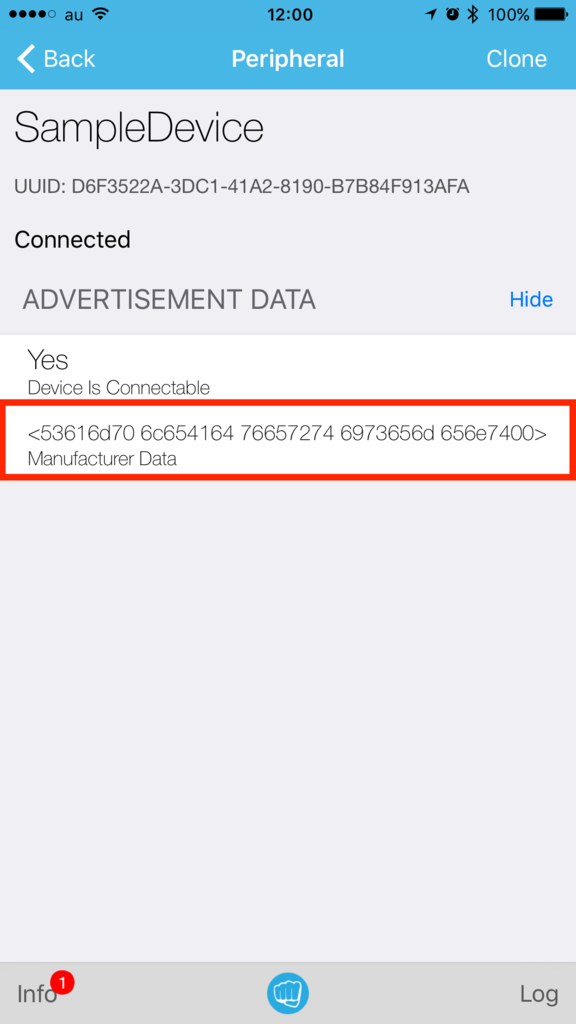
 すると Advertisement の送信が始まりますので、 iOS アプリの LightBlue などで確認すると、下記のように表示されます。

f:id:akanuma-hiroaki:20170917120410p:plain:w300 f:id:akanuma-hiroaki:20170917120439p:plain:w300

 Manufacturer Data には “SampleAdvertisement” という文字列が16進数変換されたものが表示されています。

独自サービス実装

 mbed の BLE API では下記ページに記載されている BLE Service はサポートされていますので、すぐに利用することができます。

BLE services supported on mbed - | Mbed

 例えば Heart Rate Service を使うサンプルに下記のようなものがあります。

BLE_HeartRate - a mercurial repository | Mbed

 また、カスタムのサービスを実装している例として下記のようなサンプルがあります。

BLE_Button - a mercurial repository | Mbed

 これらを参考にしてカスタムサービスを使う例を実装してみました。照度センサーからの値を扱うケースを想定して、 LuxService を実装して利用する例です。まず LuxService.h を下記のような内容で実装します。

#ifndef __BLE_LUX_SERVICE_H__
#define __BLE_LUX_SERVICE_H__

class LuxService {
public:
  const static uint16_t LUX_SERVICE_UUID = 0xA000;
  const static uint16_t LUX_VALUE_CHARACTERISTIC_UUID = 0xA001;

  LuxService(BLE &_ble, uint16_t initialValueForLUXCharacteristic) :
    ble(_ble), luxValue(LUX_VALUE_CHARACTERISTIC_UUID, &initialValueForLUXCharacteristic, GattCharacteristic::BLE_GATT_CHAR_PROPERTIES_NOTIFY)
  {
    GattCharacteristic *charTable[] = {&luxValue};
    GattService luxService(LUX_SERVICE_UUID, charTable, sizeof(charTable) / sizeof(GattCharacteristic *));
    ble.gattServer().addService(luxService);
  }

  void updateLuxValue(uint16_t newValue) {
    ble.gattServer().write(luxValue.getValueHandle(), (uint8_t *)&newValue, sizeof(bool));
  }

private:
  BLE &ble;
  ReadOnlyGattCharacteristic<uint16_t> luxValue;
};

#endif

 照度の値を扱うため、 private の変数として読み取り専用の Characteristic を luxValue として定義します。

private:
  BLE &ble;
  ReadOnlyGattCharacteristic<uint16_t> luxValue;

 コンストラクタでその Characteristic を初期化します。 Characteristic の値が更新された時に Notification を送れるように、初期化時に GattCharacteristic::BLE_GATT_CHAR_PROPERTIES_NOTIFY を渡しています。そして Service 初期化時に Characteristic を登録します。 最後に Service を GATT Server に登録します。

  LuxService(BLE &_ble, uint16_t initialValueForLUXCharacteristic) :
    ble(_ble), luxValue(LUX_VALUE_CHARACTERISTIC_UUID, &initialValueForLUXCharacteristic, GattCharacteristic::BLE_GATT_CHAR_PROPERTIES_NOTIFY)
  {
    GattCharacteristic *charTable[] = {&luxValue};
    GattService luxService(LUX_SERVICE_UUID, charTable, sizeof(charTable) / sizeof(GattCharacteristic *));
    ble.gattServer().addService(luxService);
  }

 さらに照度の値の更新用のメソッドとして void updateLuxValue(uint16_t newValue) を実装しておきます。

  void updateLuxValue(uint16_t newValue) {
    ble.gattServer().write(luxValue.getValueHandle(), (uint8_t *)&newValue, sizeof(bool));
  }

 では LuxService を利用する main.cpp の実装です。コード全体は下記のようになります。

#include "mbed.h"
#include "ble/BLE.h"
#include "LuxService.h"

DigitalOut led(LED1, 0);

const static char DEVICE_NAME[] = "LUXSample";
static const uint16_t uuid16_list[] = {LuxService::LUX_SERVICE_UUID};

static volatile bool triggerSensorPolling = false;

uint16_t luxValue = 100;
static volatile bool riseValue = true;

LuxService *luxServicePtr;

Ticker ticker;

BLE ble;

void disconnectionCallback(const Gap::DisconnectionCallbackParams_t *params)
{
  BLE::Instance().gap().startAdvertising();
}

void periodicCallback(void)
{
  led = !led;
  triggerSensorPolling = true;
}

void onBleInitError(BLE &ble, ble_error_t error)
{
}

void bleInitComplete(BLE::InitializationCompleteCallbackContext *params)
{
  BLE& ble = params->ble;
  ble_error_t error = params->error;

  if (error != BLE_ERROR_NONE) {
    onBleInitError(ble, error);
    return;
  }

  if (ble.getInstanceID() != BLE::DEFAULT_INSTANCE) {
    return;
  }

  ble.gap().setDeviceName((const uint8_t *) DEVICE_NAME);
  ble.gap().onDisconnection(disconnectionCallback);

  uint16_t initialValueForLUXCharacteristic = 100;
  luxServicePtr = new LuxService(ble, initialValueForLUXCharacteristic);

  ble.gap().accumulateAdvertisingPayload(GapAdvertisingData::BREDR_NOT_SUPPORTED | GapAdvertisingData::LE_GENERAL_DISCOVERABLE);
  ble.gap().accumulateAdvertisingPayload(GapAdvertisingData::COMPLETE_LIST_16BIT_SERVICE_IDS, (uint8_t *)uuid16_list, sizeof(uuid16_list));
  ble.gap().accumulateAdvertisingPayload(GapAdvertisingData::COMPLETE_LOCAL_NAME, (uint8_t *)DEVICE_NAME, sizeof(DEVICE_NAME));
  ble.gap().setAdvertisingType(GapAdvertisingParams::ADV_CONNECTABLE_UNDIRECTED);
  ble.gap().setAdvertisingInterval(1000);
  ble.gap().startAdvertising();
}

int main(void)
{
  ticker.attach(periodicCallback, 1);

  ble.init(bleInitComplete);

  while (ble.hasInitialized() == false) { /* spin loop */ }

  while (true) {
    if (triggerSensorPolling && ble.getGapState().connected) {
      triggerSensorPolling = false;

      if (riseValue) {
        luxValue++;
      } else {
        luxValue--;
      }

      if (luxValue == 200) {
        riseValue = false;
      } else if (luxValue == 100) {
        riseValue = true;
      }

      luxServicePtr->updateLuxValue(luxValue);
    } else {
      ble.waitForEvent();
    }
  }
}

 カスタムサービスに関連するところをピックアップして簡単に説明します。まずは先ほど実装した LuxService を include します。

#include "LuxService.h"

 UUID のリストは LuxService で定義されている UUID を使用して作成します。

static const uint16_t uuid16_list[] = {LuxService::LUX_SERVICE_UUID};

 bleInitComplete の中で LuxService を初期化します。

  uint16_t initialValueForLUXCharacteristic = 100;
  luxServicePtr = new LuxService(ble, initialValueForLUXCharacteristic);

 あとは main() の中で、センサーから取得した値(今回は擬似的に変化させている値)で LuxService の値を更新します。

      luxServicePtr->updateLuxValue(luxValue);

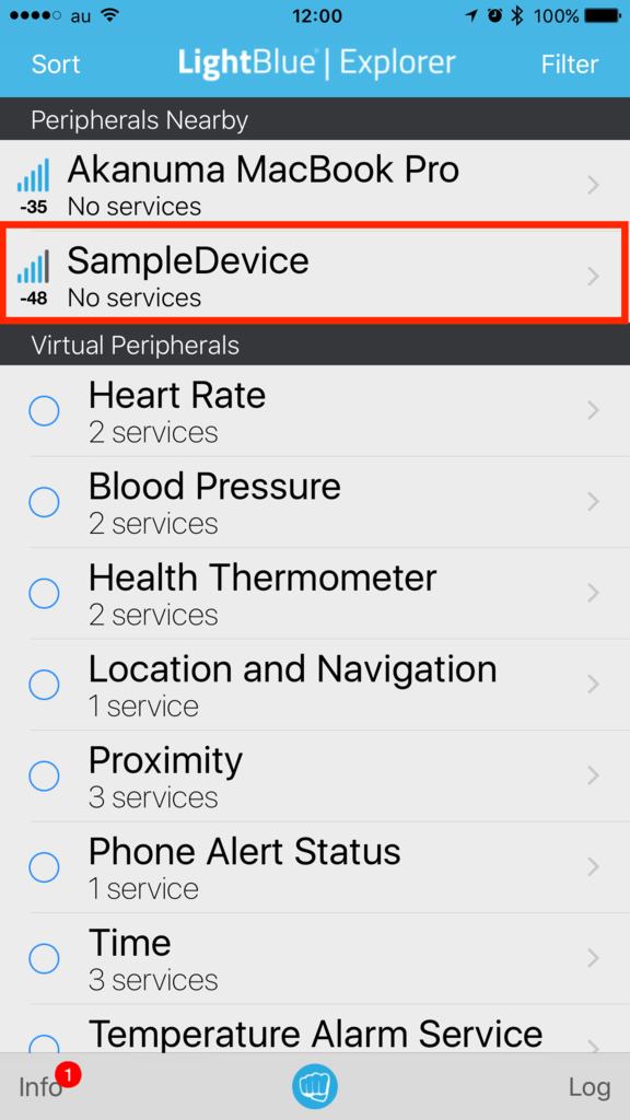
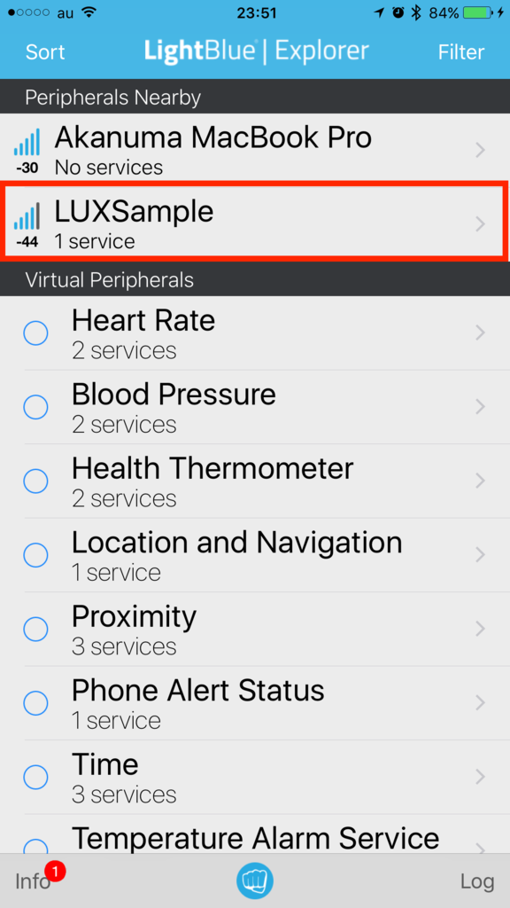
 そしてコンパイルして BLE Nano に hex ファイルをコピーし、動作を確認してみます。 LightBlue で確認すると下記のようにデバイスがリストに表示されます。

f:id:akanuma-hiroaki:20170917235501p:plain:w300

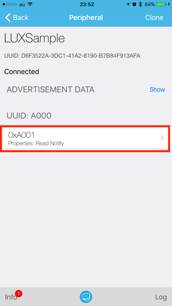
 デバイスを選択して接続すると、プロパティに Read と Notify が表示されています。

f:id:akanuma-hiroaki:20170917235622p:plain:w300

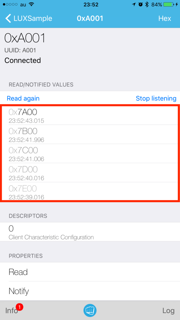
 Characteristic を選択して Notification の Listen を開始すると、毎秒照度の値が更新される度に値が表示されていきます。

f:id:akanuma-hiroaki:20170917235743p:plain:w300

まとめ

 ひとまずサンプルコードを頼りに見よう見まねで Advertisement の送信と、カスタムサービスを利用する例を実装してみました。細かいところはまだ理解できていないですが、とりあえず動かせるということはわかったので、詳細は順次確認しつつ、実際にセンサーと組み合わせて処理ができるようにしてみたいと思います。